Thermal image device and shooting method for thermal image

A technology for shooting and infrared thermal imaging, which is applied in image communication, TV, color TV parts, etc., can solve the problems of slow shooting speed, easy omission, heavy workload, etc.

Inactive Publication Date: 2012-07-04
MISSION INFRARED ELECTRO OPTICS TECH
View PDF5 Cites 94 Cited by
  • Summary
  • Abstract
  • Description
  • Claims
  • Application Information

AI Technical Summary

Problems solved by technology

[0005] However, the above method does not solve the problem. For example, high temperature is not necessarily a defect in electrical equipment, and the temperature of the hidden danger part may be low
According to the thermal imaging device of the prior art, even if the user has learned a lot of infrared shooting theory and knowledge of the subject, in the infrared detection, due to the lack of effective means, the user still needs to rely on subjective experience to select the subject when shooting. The shooting position, shooting angle and shooting distance of the subject, the shooting speed is slow, easy to miss, and the workload is heavy
[0006] In addition, because it is difficult to express the requirements for the location, angle and distance of the shooting, it is also difficult for the superior to issue clear inspection quality requirements to the subordinate

Method used


Image

  • Thermal image device and shooting method for thermal image
  • Thermal image device and shooting method for thermal image
  • Thermal image device and shooting method for thermal image

Examples


Embodiment 2

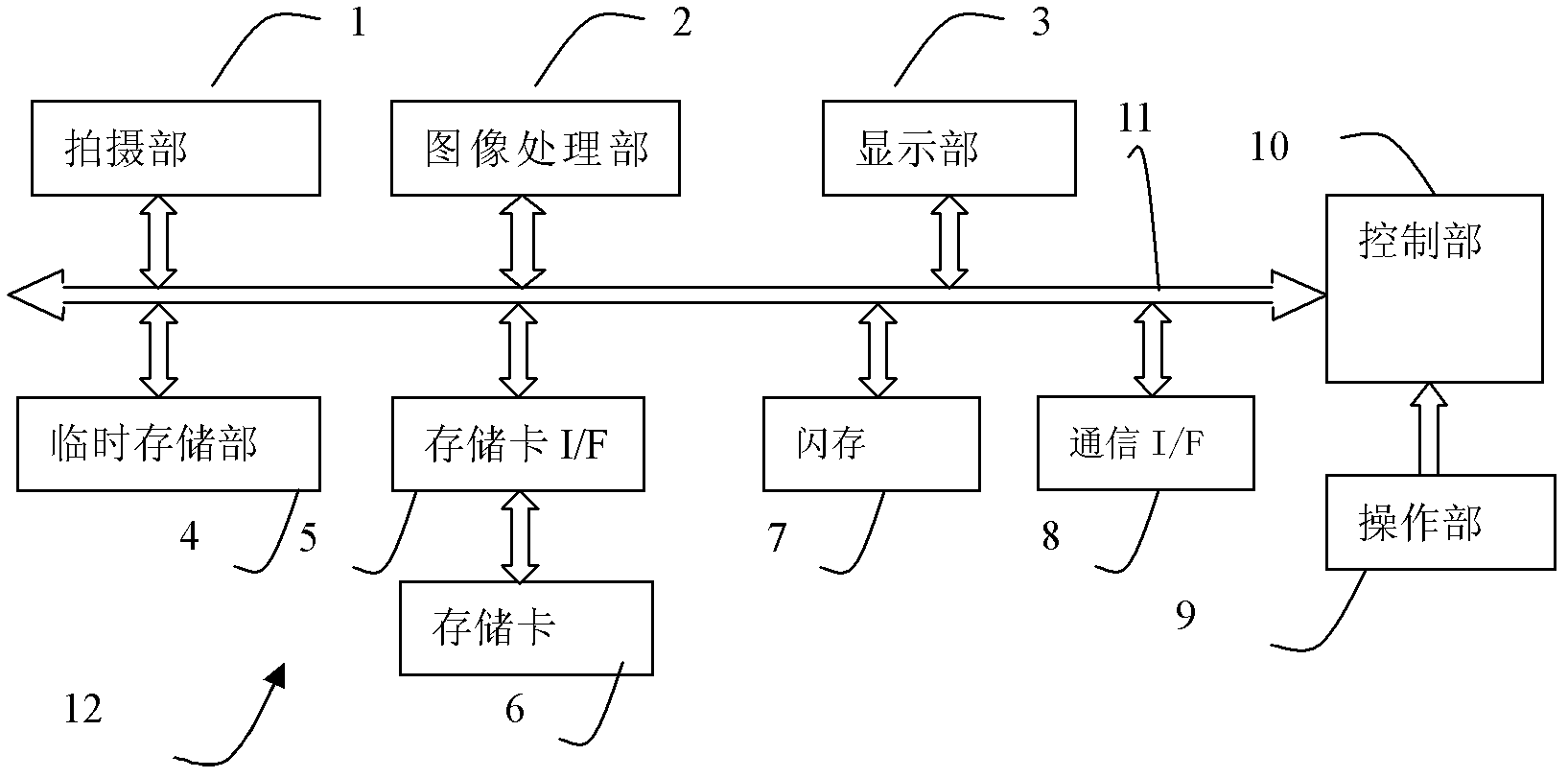
[0087] The difference from embodiment 1 is that this embodiment has the same figure 1 In the shown thermal imaging device 12 with the same structure, the flash memory 7 stores a control program for executing adaptive display of the reference image in the adaptive display area. Figure 16 It is a flowchart showing (adaptive display) reference mode processing control. Figure 17 Schematic diagram of the adaptive display effect after "centering the reference image" for the partial contour image. Figure 18 Schematic diagram of the adaptive display effect after "centering the reference range" of the local contour image. Figure 19 It is a schematic diagram of another implementation of the object information and morphological constitution data stored in the storage unit. Figure 20 It is a schematic diagram of another implementation of object information and multiple types of constituent data stored in the storage unit. Figure 21 A schematic diagram of a display interface for p...

Embodiment 3

[0106] Embodiment 3, this embodiment is with figure 1 In the thermal imaging device 12 shown with the same structure, different from the first embodiment, the flash memory 7 stores a control program for processing the determined object to obtain morphological composition data. This thermal image shooting method (processing reference mode, including processing mode and reference mode) will be described below, wherein the object designation part to be processed (control part 10) is used to designate the object to be processed; the image processing part (image processing Part 2), configured to perform at least one of processing of cutting, edge extraction, and threshold range extraction on the object to be processed; a storage portion (temporary storage portion 4, etc.), configured to store the morphological composition data obtained through processing; The reference composition determining unit (control unit 10 ) is used to determine the processed and obtained morphological comp...

Embodiment 4

[0130] This embodiment is with figure 1 In the thermal imaging device 12 with the same structure as shown, the flash memory 7 stores a control program for setting and recording related information of the configuration data. The control unit 10, the operation unit 9, and the display unit 3 are examples of the related information setting unit, which are used to set the setting information of at least one of the analysis area, object information, and indicator information corresponding to the form configuration data. 10 is used as an example of a setting recording unit to create an associated record between form configuration data and setting information.

[0131] For example, in step S303 of Embodiment 3, the morphological composition data obtained after processing is obtained. At this time, the subsequent reference mode shooting may not be performed temporarily, and the analysis area, prompt mark, and photographed area corresponding to the morphological composition data may be ...


PUM


Abstract

The invention discloses a thermal image device and a shooting method for the thermal image, and relates to the thermal image device and the field of application of infrared thermal imaging detection. According to the thermal device in the prior art, the shooting part, angle and distance of an object to be shot are selected according to subjective experience of a user during shooting; and the thermal device in the prior art is low in shooting speed, key shooting parts are missed, and the positions, sizes and angles of thermal images of similar objects which are to be shot and shot each time in infrared thermal images are almost different, so the effect of state estimation of the thermal image is influenced. According to the thermal image device and the shooting method, a specified position and size are displayed in the infrared thermal image, and the reference image of the predetermined morphological characteristics of the object to be shot is showed, expected thermal image quality of the object to be shot and the visual reference required by the shooting are provided for the user, the user is assisted in correctly grasping the imaging state and the shooting distance of the thermal image of the object to be shot, the technical requirement on the user is reduced, shooting speed is improved, and the estimation quality of the thermal image is improved.

Description

technical field [0001] The thermal imaging device and thermal image shooting method of the present invention relate to thermal imaging devices and the application field of infrared thermal image detection. Background technique [0002] As a well-known technology, a thermal imaging device forms an image by receiving infrared radiation energy of a subject, and a user judges the temperature state of the subject according to the displayed infrared thermal image. The workload of infrared inspection is heavy, such as in the power industry, a 500KV substation has hundreds of equipment to be inspected, and a single person needs to work continuously for several hours for shooting. In order to speed up the detection speed, in the infrared detection, the user usually patrols first, checks the thermal image of the subject to initially evaluate the state of the subject, and then conducts further accurate temperature measurement of the possible abnormalities found. Various subjects have ...

Claims


Application Information

Patent Timeline
Patent Type & Authority Applications(China)
IPC IPC(8): G01J5/10H04N5/33H04N5/232
Inventor 王浩
Owner MISSION INFRARED ELECTRO OPTICS TECH
Why Eureka
Try Eureka