Optical fiber coupling connector assembly and optical fiber coupling connector

A connector assembly and optical fiber coupling technology, applied in the field of optical fiber coupling connector assembly, can solve the problems of data loss, easy to be worn, and reduce the stability of optical signal transmission, and achieve the effect of preventing wear and ensuring accuracy and stability

Inactive Publication Date: 2012-07-04
HONG FU JIN PRECISION IND (SHENZHEN) CO LTD +1
View PDF2 Cites 3 Cited by
  • Summary
  • Abstract
  • Description
  • Claims
  • Application Information

AI Technical Summary

Problems solved by technology

Therefore, when the optical fiber coupling connector assembly is transported and used, the first lens and the second lens are easily worn, reducing the accuracy of optical transmission, affecting the normal use of the optical fiber coupling connector assembly, and even causing interruption of optical signals, making The transmitted data is lost thereby reducing the stability of optical signal transmission

Method used


Image

  • Optical fiber coupling connector assembly and optical fiber coupling connector
  • Optical fiber coupling connector assembly and optical fiber coupling connector
  • Optical fiber coupling connector assembly and optical fiber coupling connector

Examples


Embodiment Construction

[0047] The embodiments of the present invention will be further described in detail below in conjunction with the accompanying drawings.

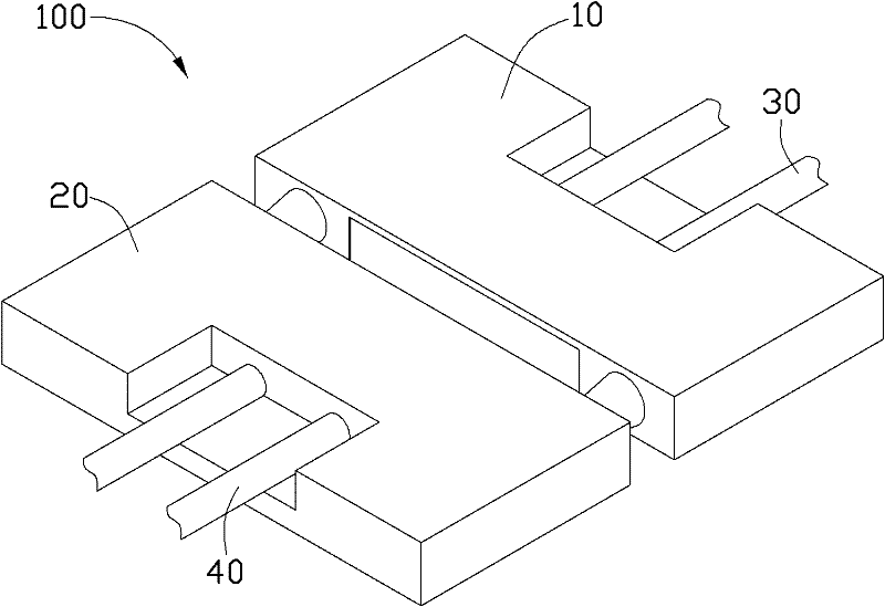
[0048] see figure 1 , is the fiber coupling connector assembly 100 according to the first embodiment of the present invention. The fiber-coupled connector assembly 100 includes a first fiber-coupled connector 10 and a second fiber-coupled connector 20 inserted into the first fiber-coupled connector 10 . After the first optical fiber coupling connector 10 and the second optical fiber coupling connector 20 are plugged together, optical signal transmission can be performed.

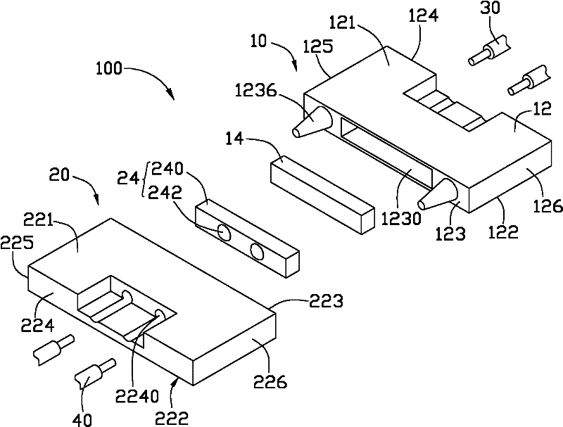
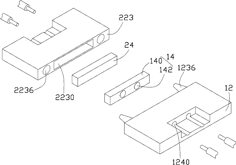
[0049] Please also refer to Figure 2 to Figure 4 , the first fiber coupling connector 10 includes a first body 12 , a first lens 14 and two first optical fibers 30 .

[0050] The first body 12 is a substantially cubic light-transmitting structure. The first body 12 includes parallel opposite top walls 121 and bottom walls 122 , parallel opposite first side walls 123 ...


PUM


Abstract

An optical fiber coupling connector assembly comprises a first optical fiber coupling connector and a second optical fiber coupling connector which are in socketed joint. The first optical fiber coupling connector comprises a first body and a first lens, the first body is provided with a first blind hole and a first containing space opposite to each other, the first lens comprises a first body and a first projection located on the first body and is fixedly arranged in the first containing space, and the first projection is located between the first blind hole and the first body and aligns to the first blind hole. The second optical fiber coupling connector comprises a second body and a second lens, the second body is provided with a second blind hole and a second containing space opposite to each other, the second lens comprises a second body and a second projection located on the second body and is fixedly arranged in the second containing space, and the second projection is located between the second blind hole and the second body and aligns to the second blind hole. The invention further relates to an optical fiber coupling connector.

Description

technical field [0001] The present invention relates to the field of Universal Serial Bus (USB), in particular to an optical fiber coupling connector and an optical fiber coupling connector assembly having the optical fiber coupling connector. Background technique [0002] At present, the use of optical signals to transmit data is gradually applied to the USB field of personal computers, and the specific form is embodied in the use of optical fiber coupling connector components. A general fiber-coupled connector assembly usually includes a first fiber-coupled connector and a second fiber-coupled connector that cooperate with each other. When in use, the first optical fiber coupling connector is inserted into the second optical fiber coupling connector, and the first lens of the first optical fiber coupling connector is aligned with the second lens of the second optical fiber coupling connector to perform optical signal transmission. [0003] However, generally, the first le...

Claims


Application Information

Patent Timeline
Patent Type & Authority Applications(China)
IPC IPC(8): G02B6/32
Inventor 余泰成吴昆展许嘉麟许义忠林奕村
Owner HONG FU JIN PRECISION IND (SHENZHEN) CO LTD
Why Eureka
Try Eureka