Visual simulation method and device

A simulation method and technology of a simulation device, applied in the field of image processing, can solve the problems of large error between the simulated sky-ground line and the actual sky-ground line, flight simulation training troubles, errors, etc., and achieve the effect of eliminating errors

Inactive Publication Date: 2012-07-04
MILITARY EQUIP RES INST AIR FORCE PLA
View PDF3 Cites 13 Cited by
  • Summary
  • Abstract
  • Description
  • Claims
  • Application Information

AI Technical Summary

Problems solved by technology

[0004] In the process of realizing the present invention, the inventors found that the prior art has at least the following problems: the simulated horizon provided by the prior art may have errors with the actual horizon, and the higher the flying altitude, the greater the difference between the simulated horizon and the actual horizon. The greater the error between
In additi

Method used


Image

  • Visual simulation method and device
  • Visual simulation method and device
  • Visual simulation method and device

Examples


Embodiment 1

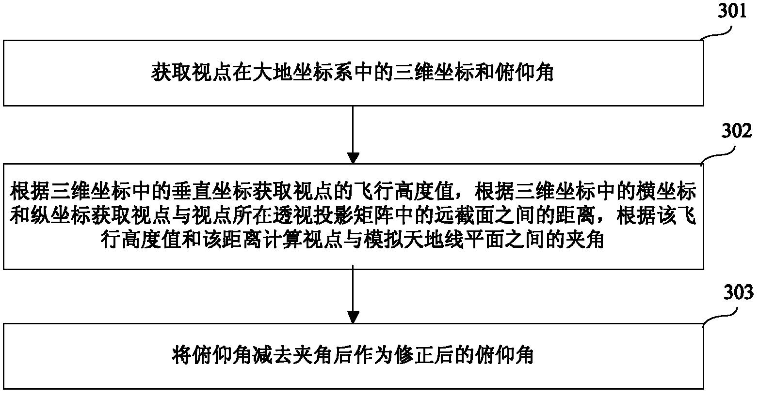
[0059] Please refer to image 3 , which shows a method flowchart of the scene simulation method provided by the embodiment of the present invention. The scene simulation method includes:

[0060] Step 301, obtaining the three-dimensional coordinates and pitch angle of the viewpoint in the earth coordinate system;

[0061] In the visual system of a flight simulator, the earth coordinate system is usually used to construct the scene. The viewpoint E is considered to be the position where the pilot observes the visual system, and is usually characterized by the coordinates of the simulated aircraft in the earth coordinate system. The coordinates of viewpoint E can be (x e ,y e ,z e , ψ, θ, γ), where x e ,y e ,z e is the three-dimensional coordinates of the viewpoint E, specifically, x e is the coordinate of the viewpoint E in the X-axis direction; y e is the coordinate of the viewpoint E in the y-axis direction, which mainly represents the flying height; z e is the coo...

Embodiment 2

[0070] Please refer to Figure 5 , which shows a method flowchart of the scene simulation method provided by Embodiment 2 of the present invention. The scene simulation method includes:

[0071] Step 501, obtaining the three-dimensional coordinates and pitch angle of the viewpoint in the earth coordinate system;

[0072] In the visual system of a flight simulator, the earth coordinate system is usually used to construct the scene. The viewpoint E is considered to be the position where the pilot observes the visual system, and is usually characterized by the coordinates of the simulated aircraft in the earth coordinate system. The coordinates of viewpoint E can be (x e ,y e ,z e , ψ, θ, γ), where x e ,y e ,z e is the three-dimensional coordinates of the viewpoint E, specifically, x e is the coordinate of the viewpoint E in the X-axis direction; y e is the coordinate of the viewpoint E in the y-axis direction, which mainly represents the flying height; z e is the coor...

Embodiment 3

[0106] Please refer to Figure 6 , which shows the scene simulation device provided by the third embodiment of the present invention. The scene simulation device includes a viewpoint coordinate acquisition module 610 , a flight height acquisition module 620 , a distance acquisition module 630 , an included angle calculation module 640 , a pitch angle correction module 650 , a horizontal plane construction module 660 and a target object correction module 670 .

[0107] The viewpoint coordinate acquisition module 610 is used to acquire the three-dimensional coordinates and pitch angle of the viewpoint in the earth coordinate system.

[0108] The flight height acquisition module 620 is configured to acquire the flight height value of the viewpoint according to the vertical coordinates in the three-dimensional coordinates obtained by the viewpoint coordinate acquisition module 610 .

[0109] The distance acquisition module 630 is configured to acquire the distance between the vie...


PUM


Abstract

The invention discloses a visual simulation method and a visual simulation device and belongs to the field of computer graphics. The method comprises the following steps of: acquiring three-dimensional coordinates and a pitching angle of a viewpoint in a geodetic coordinate system; acquiring a flight altitude value of the viewpoint according to a vertical coordinate in the three-dimensional coordinates; acquiring the distance between the viewpoint and a far section of a perspective projection matrix where the viewpoint is positioned according to a horizontal coordinate and a longitudinal coordinate in the three-dimensional coordinates; calculating an included angle between the viewpoint and a simulated horizontal plane according to the flight altitude value and the distance; and subtracting the included angle from the pitching angle to obtain a corrected pitching angle. By the invention, the pitching angle of the viewpoint is corrected, and an error between the simulated horizon and an actual horizon can be eliminated.

Description

technical field [0001] The invention relates to the field of image processing, in particular to a scene simulation method and device. Background technique [0002] As an important part of the flight simulator, the visual system can provide the pilot with a real-time view outside the cockpit that is relatively continuous with the aircraft's geographical location and attitude during flight simulation training, so that the pilot can feel personally on the scene. [0003] The visual system usually displays the scene based on the perspective projection model. The perspective projection model usually includes the viewpoint E and the viewing plane P, such as figure 1 shown. Among them, the viewpoint E can be regarded as the position of the observer, and also the angle for observing the three-dimensional world; the viewing plane P is the two-dimensional plane for drawing the perspective view of the three-dimensional object, such as the plane where the screen of the flight simulator...

Claims


Application Information

Patent Timeline
IPC IPC(8): G09B9/04G06T17/00
Inventor 雷励星范贤德
Owner MILITARY EQUIP RES INST AIR FORCE PLA
Why Eureka
Try Eureka