Gas circuit breaker
A gas circuit breaker, gas technology, applied in the direction of high-voltage air circuit breakers, circuits, electrical components, etc., can solve the problems of unable to obtain current breaking performance, unable to obtain sufficient pressure rise, pressure difference, etc.
- Summary
- Abstract
- Description
- Claims
- Application Information
AI Technical Summary
Problems solved by technology
Method used
Image

Examples
no. 1 approach
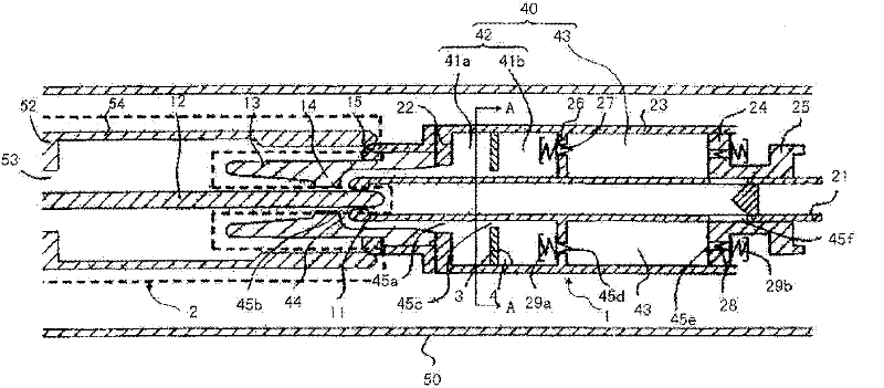
[0053] figure 1 It is a sectional view showing the structure of the gas circuit breaker of this embodiment.
[0054] The gas circuit breaker of the present embodiment includes a hollow cylindrical container 50 filled with arc-extinguishing gas, a movable contact part 1 on the central axis of the container 50, and a Opposite contact part 2 ( figure 1 The part surrounded by the dotted line), and the fixed piston 24 that is in contact with a part of the movable contact part 1 .
[0055] In addition, in figure 1 The energization state in which the movable contact part 1 and the opposing contact part 2 are in contact is shown in . Here, it is assumed that an alternating current flows in an energized state.
[0056] In the following description, the direction of the opposing contact part 2 side is defined as the front ( figure 1 the left side of the ), define its opposite side as the rear ( figure 1 to the right of the ).
[0057] In the present embodiment, the movable contac...
no. 2 approach
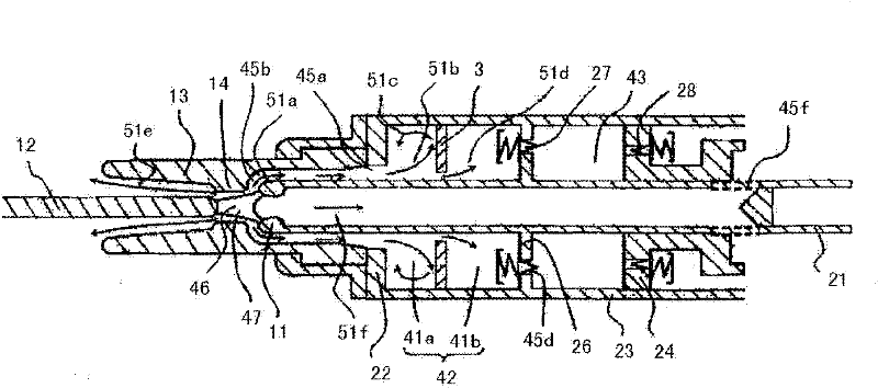
[0108] Refer to the following Figure 6 and Figure 7 The structure of the gas circuit breaker of the second embodiment will be described. here, Figure 6It is a sectional view showing the structure of the gas circuit breaker of this embodiment, Figure 7 It is a cross-sectional view showing the B-B cross-section of the gas circuit breaker of the present embodiment. In addition, the same code|symbol is attached|subjected to the same structure as 1st Embodiment, and description is abbreviate|omitted.
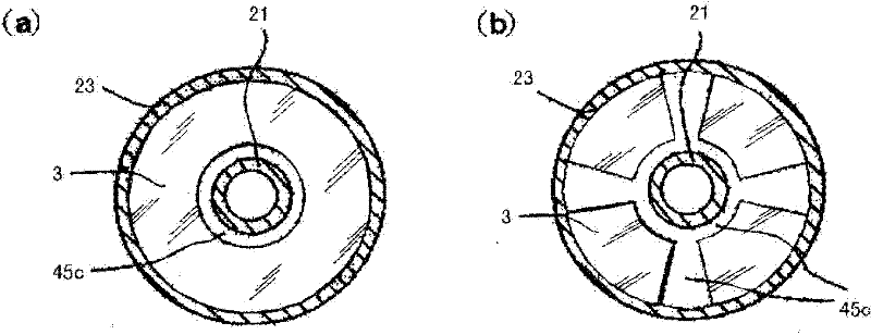
[0109] Such as Figure 6 As shown, in the gas circuit breaker of the present embodiment, the division member 3 is provided on the inner peripheral side (inner peripheral surface) of the side surface parallel to the central axis in the thermal blowing chamber 42 .
[0110] Such as Figure 7 As shown, an integral ring-shaped flat plate is used as the division member 3 , and the division member 3 is formed on the operating rod 21 forming the inner peripheral surface of the hea...
no. 3 approach
[0123] Refer to the following Figure 9 The structure of the gas circuit breaker of this embodiment is demonstrated in detail. In addition, the same code|symbol is attached|subjected to the same structure as 1st Embodiment, and description is abbreviate|omitted.
[0124] The gas circuit breaker of this embodiment does not divide the thermal blowing chamber 42 and the mechanical blowing chamber 43 by the partition wall 26, but only has the blowing chamber 48. In this point, it is different from the first embodiment, the second embodiment, and the second embodiment. Modifications of the method are different.
[0125] In the gas circuit breaker of this embodiment, the dividing member 3 is arranged on the outer peripheral side (outer peripheral surface) of the side surface parallel to the central axis in the blowing chamber 48, and divides the blowing chamber 48 into a main space 48a and a slave space 48b. At this time, as in the first embodiment, after the airflow generated by ...
PUM
 Abstract
Description
Claims
Application Information
 - R&D
- Intellectual Property
- Life Sciences
- Materials
- Tech Scout
- Unparalleled Data Quality
- Higher Quality Content
- 60% Fewer Hallucinations
Browse by: Latest US Patents, China's latest patents, Technical Efficacy Thesaurus, Application Domain, Technology Topic, Popular Technical Reports.
© 2025 PatSnap. All rights reserved.Legal|Privacy policy|Modern Slavery Act Transparency Statement|Sitemap|About US| Contact US: help@patsnap.com