Pulse welder and method of using same

a pulse welder and pulse welding technology, applied in the direction of instruments, manufacturing tools, apparatus for dispensing discrete objects, etc., can solve the problems of reducing the traveling rate of the welding operation, affecting the welding process, so as to reduce the arc force, promote shorting events, and keep the droplet size small

Active Publication Date: 2007-12-04
LINCOLN GLOBAL INC
View PDF28 Cites 132 Cited by
  • Summary
  • Abstract
  • Description
  • Claims
  • Application Information

AI Technical Summary

Benefits of technology

[0017]An advantage of the invention is that parameters of the pulse welding process can be set such as to actually promote shorting events. In such process, the transition to peak is fast to quickly start the formation of a droplet. The pulse peak time is reduced so that the droplet does not detach fully from the electrode during the peak current. The transfer of arc current to background is fast to quickly reduce the arc force on the puddle to allow it to rise and advance toward the droplet. The output current is forced below the actual background level to further promote the droplet to bridge between the electrode and the workpiece. The frequency is kept high to keep the droplet size small. When a droplet does bridge from the electrode to the puddle, the shorting response clears the short, and the plasma boost creates the next droplet on the end of the wire and forces the puddle away from the electrode.
[0018]By a plasma boost pulse between each pulse of the pulse welding process a rhythm is established that has the weld puddle moving to facilitate smooth pulses with intermediate plasma boost pulses. This allows lower spatter than obtained in a conventional pulse welding process where increased voltages cause lower spatter. The relationship of voltage and spatter by use of the present invention is shifted downwardly from the conventional relationship or operating curve of voltage / spatter. At any voltage, spatter is lower using the invention.
[0019]Because of the stability of the plasma boost, the process can be run at levels where every droplet is transferred through a short circuit, thereby significantly reducing the heat input of the welding process. The ability to transfer metal across a short circuit infers that the electrode, i.e. solid wire, metal cored wire, or flux cored wire, is stable in a short circuit transfer mode. Such as the case with many steel, stainless, aluminum solid wires, the present invention can improve the welding performance at shorter arc lengths. Metal cored wires with a stable short arc performance such as Lincoln Electric's MS-6 ad MC-706 wire can benefit from the present invention. Utilizing the present invention, these wires have the improved ability to handle poor fit up conditions and faster travel speeds. These wires include an effective amount of sulfur to cause the wire to operate uniformly during short circuit transfer of metal.
[0020]The invention is a refined pulse welding process designed specifically to allow faster speeds than standard pulse waveforms. It improves low voltage welding at high speeds, as it stabilizes the process with shortened arc length. With conventional waveforms, the arc length is kept longer to avoid spatter, thus limiting travel speed. In the invention, the arc length is kept short and tight and spatter is avoided with control of the short circuit cycle. Thus, the shorter arc is stabilized with rhythmic short circuit cycles. The treatment of the short circuit reduces stubbing and spatter.
[0021]The primary object of the present invention is the provision of an electric arc welder, which welder utilizes a plasma boost pulse after a short circuit has been cleared and before the next adjacent pulse for melting and transferring molten metal to the weld puddle.
[0022]Another object of the present invention is the provision of an electric arc welder, as defined above, which welder can be operated at high speed, with a short arc length and / or with metal cored of flux cored wires. When using metal cored electrodes, the core has an effective amount of sulfur to improve the shape of the weld bead at high travel speeds.

Problems solved by technology

An interruption in the normal operation of a pulse welding process occurs when the molten metal contacts the workpiece before being released from the advancing wire.
In summary, short circuits cause reduced quality of the weld and reduce the traveling rate of the welding operation, as well as requiring high voltage with its disadvantages.
These short circuits are more troublesome when attempting to use the metallurgical advantage of metal cored electrodes.
They also cause spatter during breaking of the short circuit.
This resulted in the need to operate at lower travel speeds.
Furthermore, spatter and non-uniform weld beads resulted when high voltages and normal short circuit clearing was employed.
As the arc length is reduced, shorting events become more frequent and become harder to clear.
When the short does break at high current, spatter typically occurs and an accompanying instability will follow as the high current pushes down on the puddle causing an oscillation.
This problem is sometimes caused by repetitive shorting.
As a short is cleared, another short immediately forms and is difficult to clear.
However, in use of solid wires, these cored wires exhibit an increase in the frequency and severity of short circuits as the arc length is reduced.
Thus, the advantage associated with cored electrodes can not be fully employed.

Method used


Image

  • Pulse welder and method of using same
  • Pulse welder and method of using same
  • Pulse welder and method of using same

Examples


Embodiment Construction

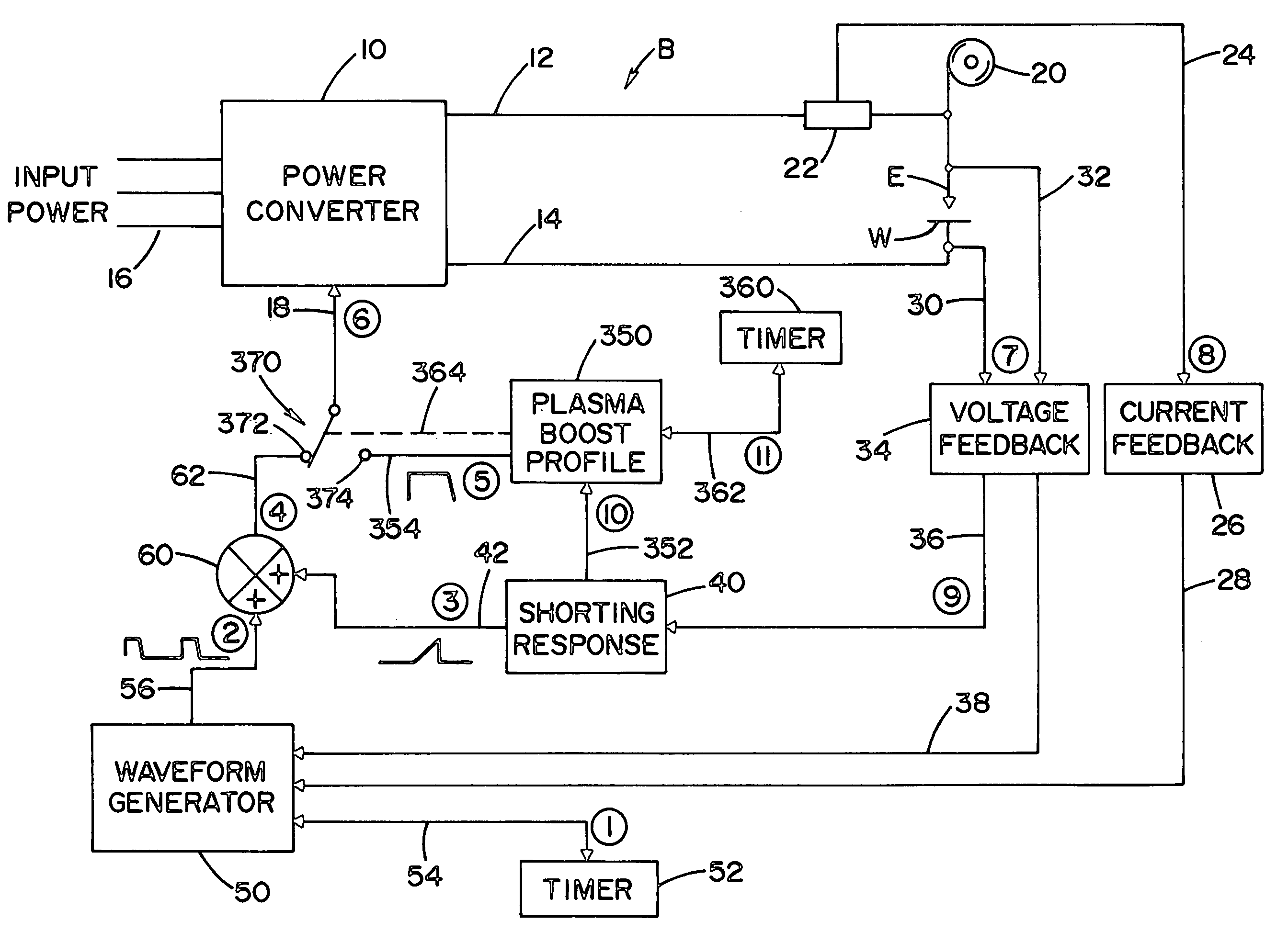
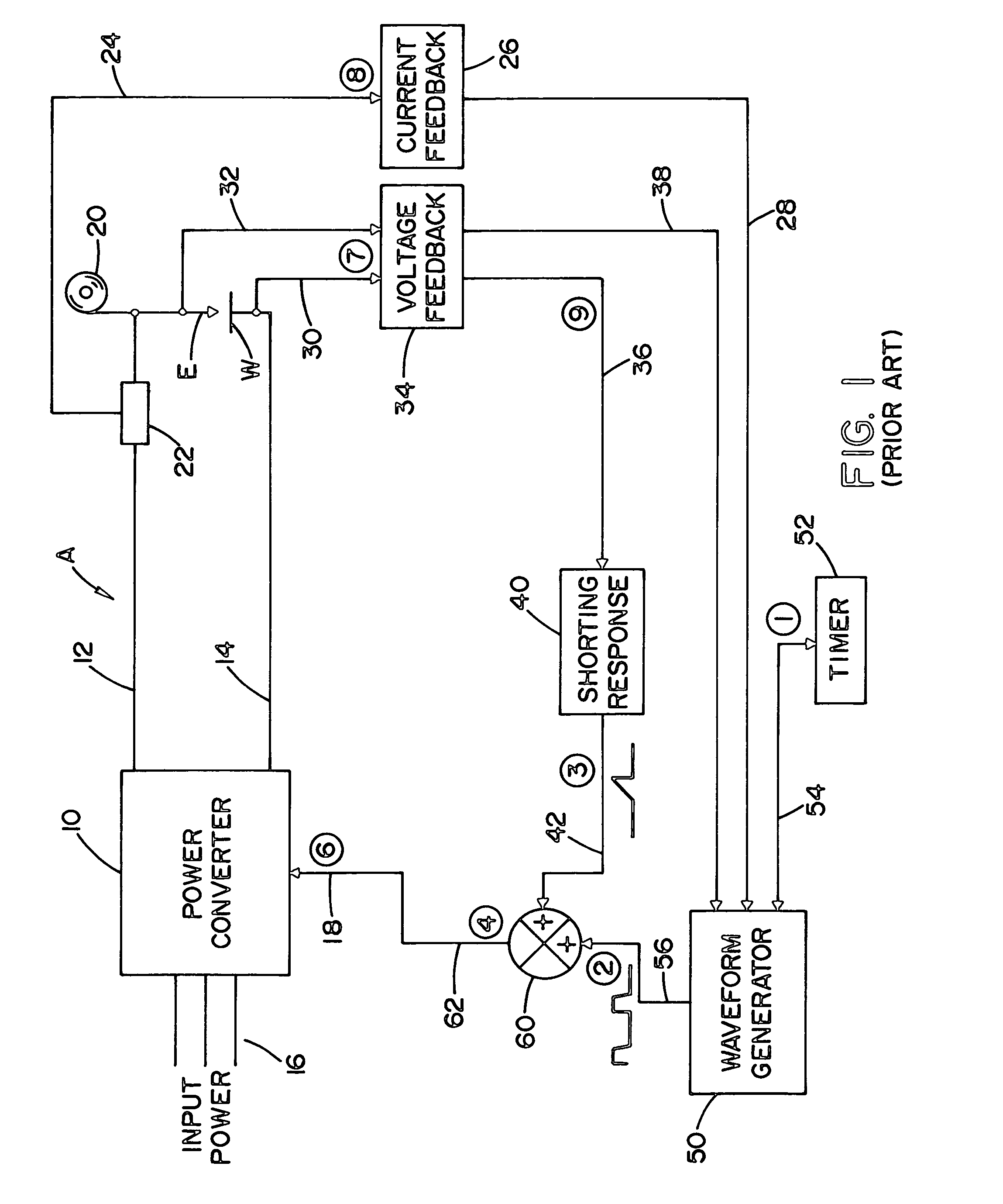
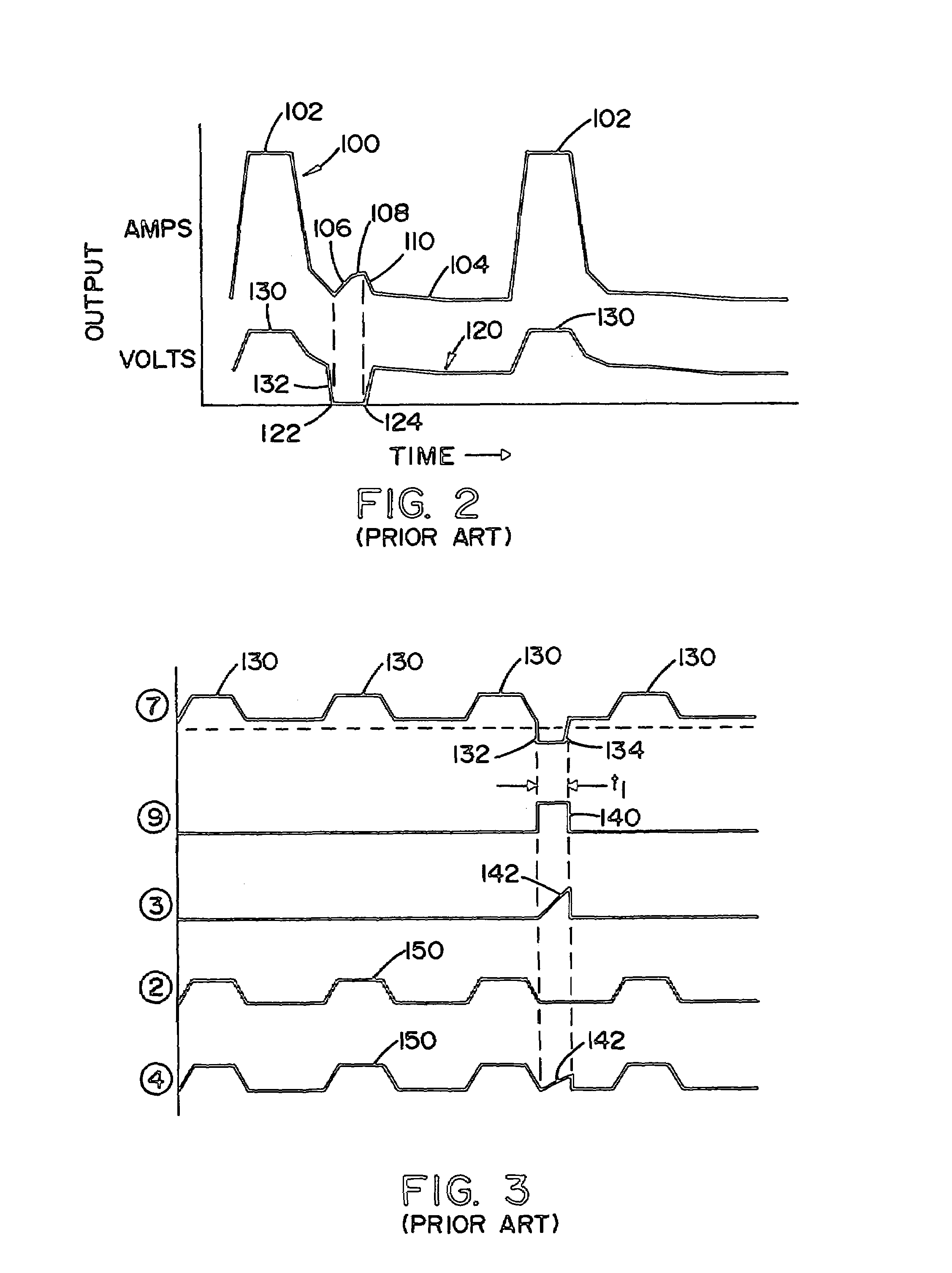
[0052]Referring now to the drawings, wherein the showings are for the purpose of illustrating a preferred embodiment of the invention only and not for the purpose of limiting same, FIGS. 1-3 illustrate a prior art electric arc welder A for performing a pulse welding process, as shown in FIG. 2. The prior art is illustrated since the components used in practicing the invention are essentially the same as standard components in electric arc welder. Although other welder architecture could be used, the preferred architecture is a welder controlled by waveform technology as pioneered by The Lincoln Electric Company of Cleveland, Ohio. Two of many patents relating to waveform technology is described in Blankenship U.S. Pat. No. 5,278,390 and Fulmer U.S. Pat. No. 6,498,321, incorporated by reference herein as background information. In this type of welder, a waveform generator produces the profile for the waveforms used in a pulse welding process. The power source creates the pulses in ac...


PUM

PropertyMeasurementUnit
voltageaaaaaaaaaa
arc lengthaaaaaaaaaa
frequencyaaaaaaaaaa

Abstract

An electric arc welder for performing a pulse welding process by a current between an advancing electrode and workpiece where the welder comprises a short detecting circuit for creating a short signal upon occurrence of a short circuit between the advancing electrode and the workpiece and a boost circuit to create a plasma boost pulse after the short circuit is cleared during the time period when the welder is not outputting the peak pulse current.

Description

[0001]The present invention relates to a novel electric arc welder and more particularly to an electric arc welder for performing a novel pulse welding process and the method of pulse welding using the novel arc welder.BACKGROUND OF INVENTION[0002]In electric arc welding, one of the most popular welding process is pulse welding which primarily uses a solid wire electrode with an outer shielding gas. MIG welding utilizes spaced pulses which first melt the end of an advancing wire and then propel the molten metal from the end of the wire through the arc to the workpiece. Under ideal conditions, a globular mass of molten metal is melted and transferred during each pulse of the pulse welding process. An interruption in the normal operation of a pulse welding process occurs when the molten metal contacts the workpiece before being released from the advancing wire. Consequently, the high voltage pulse welding of over 25 volts is normally used so that the gap between the end of the electro...

Claims


Application Information

Patent Timeline
Patent Type & Authority Patents(United States)
IPC IPC(8): B23K9/09B23K9/073
CPCB23K9/09B23K9/0738G07F17/0071G07F11/58G07F9/105
Inventor FULMER, BRUCE E.HEARN, JAMES E.HSU, CHRISTOPHERPETERS, STEVEN R.
Owner LINCOLN GLOBAL INC
Why Eureka
Try Eureka