[0017] An
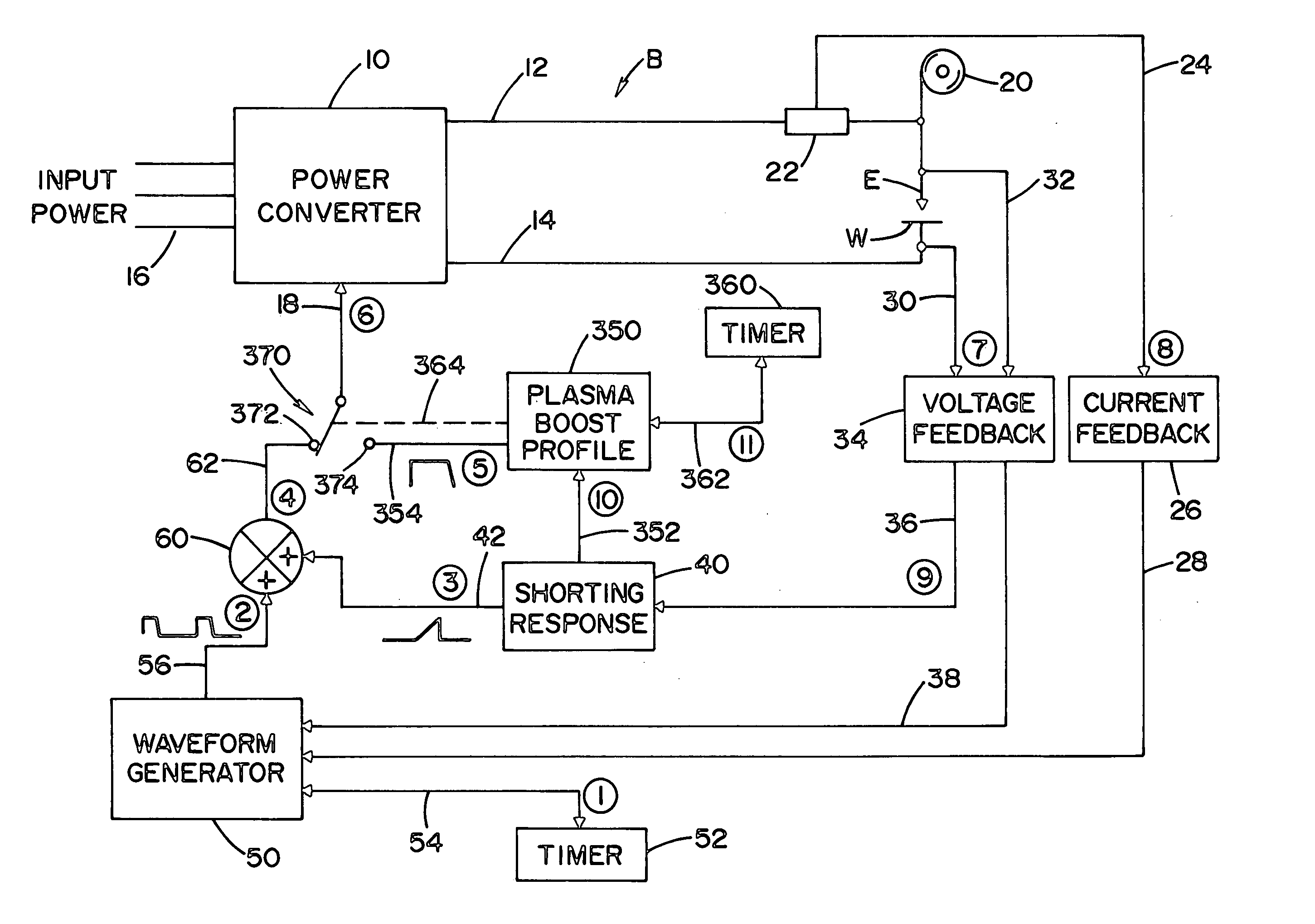
advantage of the invention is that parameters of the pulse welding process can be set such as to actually promote shorting events. In such process, the transition to peak is fast to quickly start the formation of a droplet. The pulse peak time is reduced so that the droplet does not detach fully from the electrode during the
peak current. The transfer of arc current to background is fast to quickly reduce the arc force on the
puddle to allow it to rise and advance toward the droplet. The output current is forced below the actual
background level to further promote the droplet to bridge between the electrode and the workpiece. The frequency is kept high to keep the
droplet size small. When a droplet does bridge from the electrode to the
puddle, the shorting response clears the short, and the
plasma boost creates the next droplet on the end of the wire and forces the puddle away from the electrode.
[0018] By a
plasma boost pulse between each pulse of the pulse welding process a
rhythm is established that has the weld puddle moving to facilitate smooth pulses with intermediate plasma boost pulses. This allows lower spatter than obtained in a conventional pulse welding process where increased voltages cause lower spatter. The relationship of
voltage and spatter by use of the present invention is shifted downwardly from the conventional relationship or operating curve of
voltage / spatter. At any
voltage, spatter is lower using the invention.
[0019] Because of the stability of the plasma boost, the process can be run at levels where every droplet is transferred through a short circuit, thereby significantly reducing the heat input of the welding process. The ability to transfer
metal across a short circuit infers that the electrode, i.e.
solid wire, metal cored wire, or flux cored wire, is stable in a short circuit
transfer mode. Such as the case with many steel, stainless, aluminum solid wires, the present invention can improve the welding performance at shorter arc lengths.
Metal cored wires with a stable short arc performance such as Lincoln Electric's MS-6 ad MC-706 wire can benefit from the present invention. Utilizing the present invention, these wires have the improved ability to
handle poor fit up conditions and faster travel speeds. These wires include an effective amount of
sulfur to cause the wire to operate uniformly during short circuit transfer of metal.
[0020] The invention is a refined pulse welding process designed specifically to allow faster speeds than standard pulse waveforms. It improves
low voltage welding at high speeds, as it stabilizes the process with shortened
arc length. With conventional waveforms, the arc length is kept longer to avoid spatter, thus limiting travel speed. In the invention, the arc length is kept short and tight and spatter is avoided with control of the short circuit cycle. Thus, the shorter arc is stabilized with rhythmic short circuit cycles. The treatment of the short circuit reduces stubbing and spatter.
[0021] The primary object of the present invention is the provision of an electric arc welder, which welder utilizes a plasma boost pulse after a short circuit has been cleared and before the next adjacent pulse for melting and transferring molten metal to the weld puddle.
[0022] Another object of the present invention is the provision of an electric arc welder, as defined above, which welder can be operated at high speed, with a short arc length and / or with metal cored of flux cored wires. When using metal cored electrodes, the core has an effective amount of
sulfur to improve the shape of the
weld bead at high travel speeds.


