Three stage power source for electric ARC welding

a power source and electric arc technology, applied in the energy industry, efficient power electronics conversion, manufacturing tools, etc., can solve the problems of switching losses, higher current and voltage stresses, and higher switching speeds, so as to improve portability, high switching speeds, and control system the effect of band width

Active Publication Date: 2006-09-28
LINCOLN GLOBAL INC
View PDF101 Cites 131 Cited by
  • Summary
  • Abstract
  • Description
  • Claims
  • Application Information

AI Technical Summary

Benefits of technology

[0015] There are several benefits to operating welding inverters with high switching speeds. For instance, smaller magnetics translate into improved portability. Another advantage is the potential to have a higher band width control system, which system will result in a better arc performance. Thus, the novel three stage power source described above is improved by the present invention. This background three stage power source has power switches operated at extremely high switching speed, exceeding 18 kHz. The boost power switch for the first stage and the four power switches for the unregulated second stage are all operated at high frequency to obtain the benefit of high switching speed. There is a downside to the use of such higher switching speeds. Such switching speeds cause switching losses. If the switching losses are not reduced the power source efficiency and reliability are decreased. The switching ...

Problems solved by technology

There is a downside to the use of such higher switching speeds.
Such switching speeds cause switching losses.
However, this type of prior soft switching control often causes higher current and voltage stresses because of the s...

Method used


Image

  • Three stage power source for electric ARC welding
  • Three stage power source for electric ARC welding
  • Three stage power source for electric ARC welding

Examples


Embodiment Construction

FIGS. 22-24

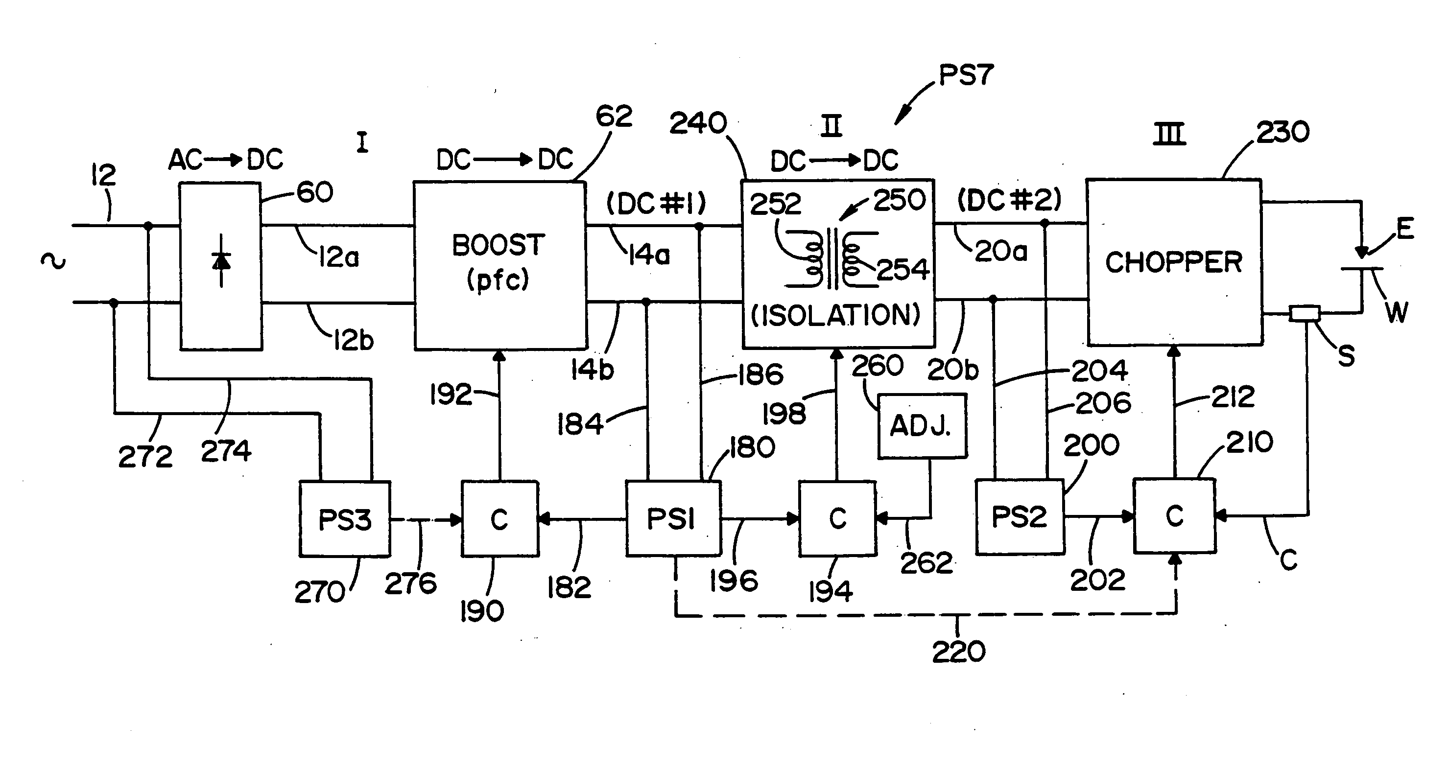
[0056] In FIG. 22 the first two stages of the improved three stage power source includes unregulated converter A as best shown in FIG. 17 wherein the input DC signal across lines 14a, 14b is provided by a novel first input stage shown as boost converter 600 having power switch 602 switched by a gate signal in line 604. Switch 602 is turned on after auxiliary switch 628 is turned on. The timing of gating signals in lines 192 and 192a is by power factor correcting controller 194. A high frequency signal in line 192 causes a high frequency switching signal in gate 604 of main power switch 602 with anti-parallel diode 602a, in accordance with standard boost technology. The timing of the signal on gate 604 is controlled in accordance with previous discussions to obtain power factor correction for the power supply creating the rectified signal on input leads 12a, 12b. The DC signal at leads 12a, 12b is converted by switch 602 and output rectifier diode 610 into a DC bus at lead...


PUM

PropertyMeasurementUnit
Fractionaaaaaaaaaa
Fractionaaaaaaaaaa
Poweraaaaaaaaaa

Abstract

A three stage power source for an electric arc welding process comprising an input stage having an AC input and a first DC output signal; a second stage in the form of an unregulated DC to DC converter having an input connected to the first DC output signal, a network of switches switched at a high frequency with a given duty cycle to convert the input into a first internal AC signal, an isolation transformer with a primary winding driven by the first internal high frequency AC signal and a secondary winding for creating a second internal high frequency AC signal and a rectifier to convert the second internal AC signal into a second DC output signal of the second stage, with a magnitude related to the duty cycle of the switches; and, a third stage to convert the second DC output signal to a welding output for welding wherein the input stage has a regulated DC to DC converter with a boost power switch having an active soft switching circuit.

Description

[0001] The invention relates to the field of electric arc welding and more particularly to an improved three stage power source for such welding and a novel relationship between the first two stages of the three stage power source. INCORPORATION BY REFERENCE AND BACKGROUND OF INVENTION [0002] Electric arc welding involves the passing of an AC or DC current between a metal electrode and a workpiece where the metal electrode is normally a cored metal wire or solid metal wire. A power source is used to create a given current pattern and / or polarity between the advancing electrode wire and workpiece so that the arc will melt the end of the advancing welding wire and deposit the molten metal on the workpiece. Although various converter technologies are used for power sources, the most effective is an inverter based power source where a switching network includes switches operated at high frequency to create the desired waveform or current level for the welding process. An inverter type p...

Claims


Application Information

Patent Timeline
IPC IPC(8): B23K9/10
CPCB23K9/095B23K9/1043H02M1/4225H02M3/158H02M2001/007Y02B70/1425H02M7/487Y02B70/10Y02P70/10Y02P80/10H02M1/0006H02M1/342H02M1/007H02M1/0085B23K9/09B23K9/10
Inventor KOOKEN, TODD E.LUO, LIFENG
Owner LINCOLN GLOBAL INC
Why Eureka
Try Eureka