Three-speed temperature controlled power switch

A power switch and medium temperature technology, applied in the direction of thermal switch components, etc., can solve the problem that temperature control materials cannot respond quickly to temperature changes and deformation, and achieve the effect of rapid and accurate response, fast speed and stable structural state

Inactive Publication Date: 2015-07-01
LONGKOU ZHONGYU MACHINERY
View PDF4 Cites 0 Cited by
  • Summary
  • Abstract
  • Description
  • Claims
  • Application Information

AI Technical Summary

Problems solved by technology

[0007] The purpose of the present invention is to provide a three-speed temperature-controlled power switch, which solves the problem that the temperature-controlled material cannot quickly respond to temperature changes to produce deformation, and accurately transmits the deformation force to the switch contacts, and completes the technology of closing or opening different subsequent circuits in time question

Method used


Image

  • Three-speed temperature controlled power switch
  • Three-speed temperature controlled power switch
  • Three-speed temperature controlled power switch

Examples


Embodiment 1

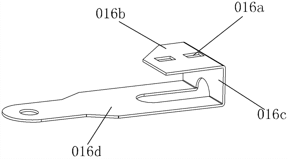
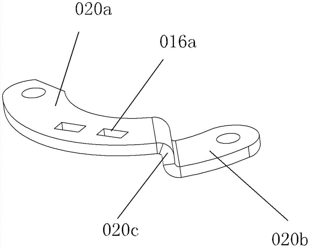
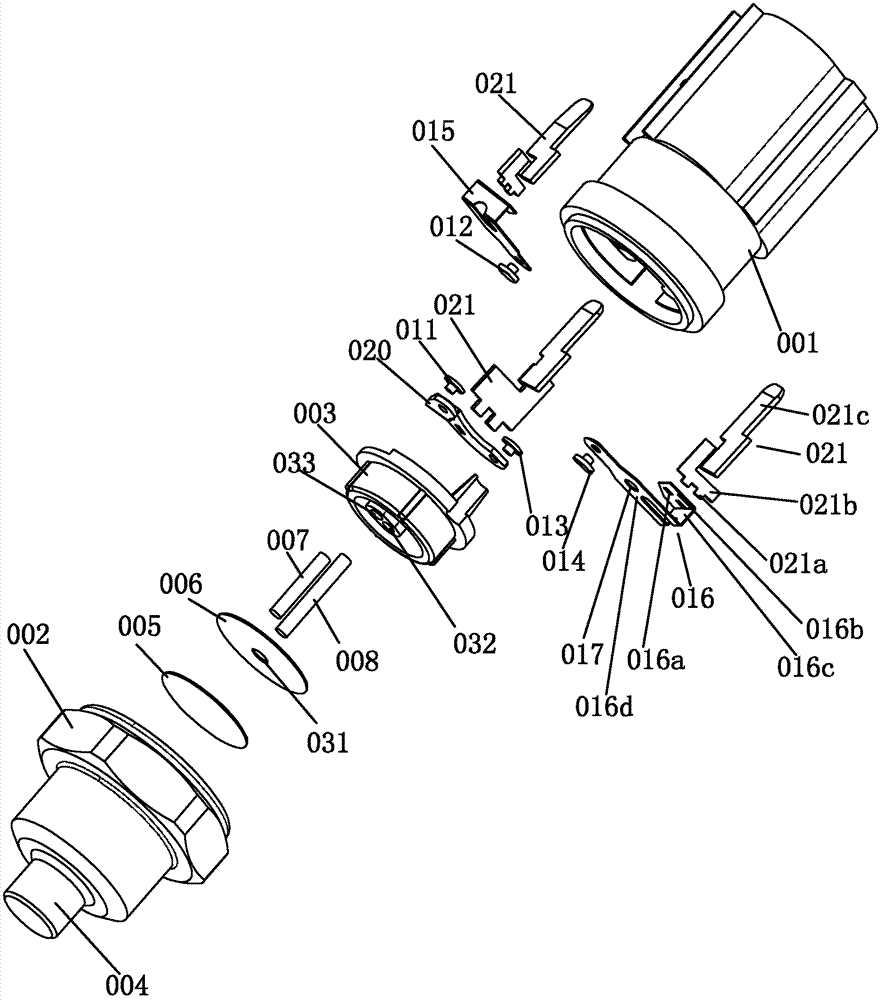
[0050] The transmission device of embodiment 1 includes a medium-temperature bimetallic strip 005, a high-temperature bimetallic strip 006, a first push rod 008, a second push rod 007, a fixed contact piece 020, a first movable contact piece 015, and a second movable contact piece 016. Such as Figure 4 As shown, the medium temperature bimetal 005 is placed on the first platform 009 at the bottom of the sensor housing 002, the high temperature bimetal 006 is placed on the second platform 010, the passive layer of the medium temperature bimetal 005 and the high temperature bimetal The passive layers of the metal sheet 006 are adjacent. Such as Image 6 , Figure 7 with Figure 8 As shown, the upper end surface of one end of the fixed contact 020 is provided with a first contact 011, and the upper end of the other end is provided with a second contact 013. The fixed contact 020 is bent so that there is a gap between the first contact 011 and the second contact 013. Height di...


PUM


Abstract

A three-speed temperature controlled power switch comprises a moderate-temperature bimetallic strip, a high-temperature bimetallic strip, a first push rod, a second push rod, a first movable contact piece, a second movable contact piece, fixed contact pieces and conducting strips, wherein a first ladder stand and a second ladder stand, which are arranged at the bottom of the inner chamber of a sensor housing from the bottom up, are used for placing the bimetallic strips; the high-temperature bimetallic strip and the moderate-temperature bimetallic strip are similar in structure; the round disc-shaped moderate-temperature bimetallic strip comprises a first active metal layer and a first passive metal layer which are in tight connection and in double-layer structures; and the upper end surface of the first active metal layer and the lower end surface of the first passive metal layer are cambered surfaces where the first active metal layer sinks toward the first passive metal layer. The three-speed temperature controlled power switch provided by the invention can ensure that the temperature sensitive metal pieces can deform timely and quickly, and the deformation can be accurately transmitted to a switch contact, thereby controlling of the connection and disconnection of a contact connection circuit.

Description

technical field [0001] The invention relates to a temperature-controlled power switch, in particular to a temperature-controlled switch with multiple trigger conditions. Background technique [0002] It is generally believed that the heat dissipation and cooling method of the car engine is mainly to use the fan to cool the water tank of the engine thermal cycle system. Once the engine is started, the fan will be set to run at full speed regardless of the temperature of the water tank. When the engine is just started or the ambient temperature is low, the operation of the fan will cause the engine to fail to reach the optimum working temperature for a long time, resulting in unnecessary waste of energy, which in turn affects environmental protection. [0003] The operation mode of the fan can be changed by adding a temperature-controlled power switch and an electromagnetic fan clutch, so that the fan starts when the temperature of the water tank reaches a certain limit value....

Claims


Application Information

Patent Timeline
Patent Type & Authority Patents(China)
IPC IPC(8): H01H37/52
Inventor 王兆宇邢子义李芳
Owner LONGKOU ZHONGYU MACHINERY
Why Eureka
Try Eureka