Crystal boat converter

A converter and positioning area technology, which is applied in semiconductor/solid-state device manufacturing, conveyor objects, electrical components, etc., can solve problems such as wafer fragmentation, wafer falling out of the wafer boat, collision, etc.

Inactive Publication Date: 2012-07-04
CHIPMOS TECH INC
View PDF6 Cites 4 Cited by
  • Summary
  • Abstract
  • Description
  • Claims
  • Application Information

AI Technical Summary

Problems solved by technology

[0005] In the whole process of wafer transfer, the operator must follow the specified sequence and action posture. Although the existing wafer boat changer has a positioning device to guide the operator to position the wafer boat, when placing the wafer boat However, there is no positioning device to help confirm whether the opening of the wafer boat is facing the correct direction. If the opening of the wafer boat is facing in the wrong direction, the wafer may collide with the wafer boat to receive the wafer during the wafer transfer process, and then Risk of wafer breakage
[0006] At the same time, after the wafer transfer operation of the existing wafer boat converter is completed, the wafer boat must be taken out according to the prescribed sequence and action posture. If the operator does not notice for a while, the wafer boat will be taken out in the wrong posture. , the wafers in the wafer boat may fall out of the wafer boat, resulting in high losses, so how to safely and efficiently complete the work of converting wafers on the wafer boat converter, so that operators can operate more efficiently Convenience and reducing the risk of wafer damage, and how to develop a wafer boat converter that can reduce human error during wafer removal are very important issues

Method used


Image

  • Crystal boat converter
  • Crystal boat converter
  • Crystal boat converter

Examples


Embodiment Construction

[0055] Since the present invention discloses a wafer boat converter, the manner of wafer boat conversion used therein has been understood by those with ordinary knowledge in the relevant technical field, so it will not be fully described in the following description. At the same time, the following diagrams are used to express the structural representations related to the features of the present invention, and they are not and need not be completely drawn according to the actual size, so they will be described first.

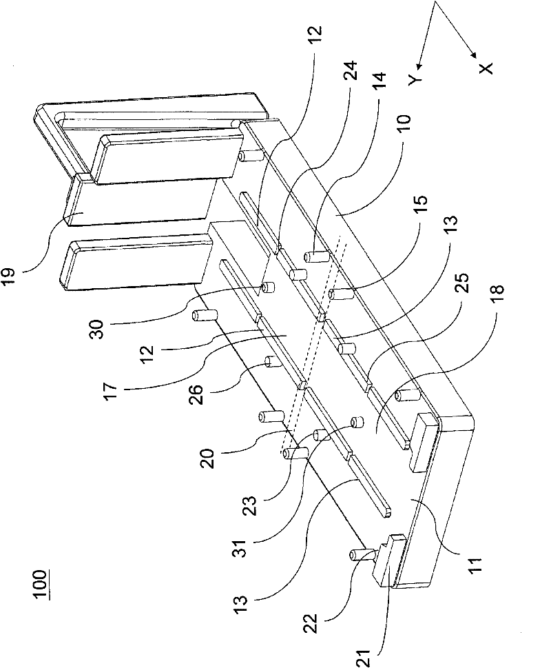
[0056] Please refer to Figure 1 to Figure 2 , is a first preferred embodiment proposed according to the present invention, which is a wafer converter 100 . This crystal boat converter 100 includes a base 10, the base 10 has a carrying plate 11, a first positioning guide rail 12, a second positioning guide rail 13, a first guiding device 14 and a second guiding device 15, and the carrying plate 11 is further A first positioning area 17 and a second positioning ...


PUM


Abstract

The present utility model provides a crystal boat converter which comprises a pedestal, the pedestal is provided with a bearing plate, a first positioning area and a second positioning area are further formed along the first direction on the bearing plate, and a first blocking device is arranged on the bearing plate, specifically on the outer edge of one end of the second positioning area, which is far away from an spacing part. The height of the first blocking device is larger than the width of the spacing part, a blocking surface is formed by the first blocking device, and the blocking surface is faced with the spacing part. The second positioning area also comprises a second blocking device which is protruded on the bearing plate, thus operating personnel can be ensured by the first and second blocking devices to displace or fetch the crystal boat in a correct direction, thus the safety of wafers can be increased.

Description

【Technical field】 [0001] The present invention relates to a wafer changer, in particular to a manual wafer changer with a fool-proof function. 【Background technique】 [0002] In the general semiconductor manufacturing process, wafers need to be processed by various machines. When the wafers are switched or moved, they will be placed in wafer boats to ensure the safety of the wafers. In order to match the machines required for different processes In the process environment, wafers often need to be stored in wafer boats of different configurations, and when wafers are to be transferred between different wafer boats, a wafer transfer (Wafer Transfer) will be used to assist wafers in the two wafer boats safely exchange position. The concept of using the wafer boat changer is that the operator first places the wafer boat to be transferred out and the wafer boat to receive wafers on the designated positions on the wafer boat changer in sequence, and after confirming that the two ...

Claims


Application Information

Patent Timeline
Patent Type & Authority Applications(China)
IPC IPC(8): H01L21/67H01L21/677H01L21/68
Inventor 田金德章铭祥张竣雄
Owner CHIPMOS TECH INC
Why Eureka
Try Eureka