
Microwave four-frequency band pass filter

A filter and four-band technology, which is applied in the field of four-band bandpass filters, can solve the problems of complex coupling structure and difficult adjustment of bandwidth, and achieve the effect of large bandwidth ratio, simple circuit and large isolation

Inactive Publication Date: 2014-05-21
NANJING UNIV OF AERONAUTICS & ASTRONAUTICS
View PDF2 Cites 0 Cited by
  • Summary
  • Abstract
  • Description
  • Claims
  • Application Information

AI Technical Summary

Problems solved by technology

[0007] In view of the defects in the existing multi-frequency band-pass filter technology, the present invention proposes a microwave four-band band-pass filter to solve the problems of complex coupling structure and difficult bandwidth adjustment.

Method used


Image

  • Microwave four-frequency band pass filter
  • Microwave four-frequency band pass filter
  • Microwave four-frequency band pass filter

Examples


Embodiment Construction

[0022] The structure and principle of the present invention will be further described below.

[0023] figure 1 A topology structure of a dual-frequency bandpass filter is given. The dual-frequency resonator is a two-section ladder impedance short-circuit stub, which is connected by two transmission lines with different characteristic impedances. The terminal is short-circuited. Its input admittance for:

[0024] Y in ( ω ) = - j Z s 2 Z s 2 - Z s 1 tan θ s 1 ...


PUM


Abstract

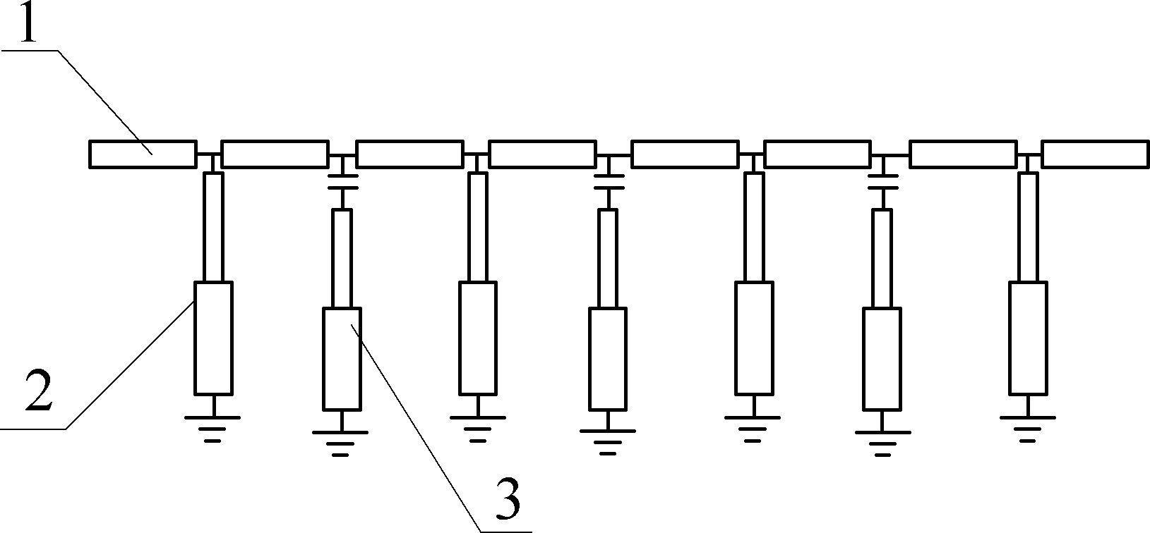
The invention discloses a microwave four-frequency band pass filter, belonging to the field of multi-frequency band pass filters. The microwave four-frequency band pass filter is formed by mutually embedding a double-frequency band pass filter and a double-frequency band elimination filter circuit, particularly the microwave four-frequency band pass filter is formed by alternatively loading n dual-mode resonators and n-1 double-frequency band stop units on a transmission line, all terminals of the dual-mode resonators and the double-frequency band stop units have short circuit, and a stop band of the double-frequency band stop unit is arranged in a pass band frequency range of the double-frequency band pass unit. The microwave four-frequency band pass filter disclosed by the invention avoids the usage of a complex coupling network and has the advantages of simple circuit, small total length and larger isolation degree.

Description

technical field [0001] The invention relates to a filter, in particular to a four-frequency band-pass filter, which belongs to the field of multi-frequency band-pass filters. Background technique [0002] The realization of the existing multi-frequency bandpass filter generally has two forms: [0003] 1) Multiple sets of resonator schemes. Multiple groups of resonators are used to implement a multi-frequency bandpass filter, and each group of resonators implements a passband respectively, and has a separate coupling network, or a part of the coupling network is shared. This multi-frequency band-pass filter actually uses a resonator several times larger than that of a single-pass band filter. In addition, a complex coupling network needs to be arranged, and the circuit structure arrangement is very cramped. If a high-order multi-frequency band-pass filter is to be realized, the coupling Structural arrangements will be more difficult. The circuit of this filter is inefficie...

Claims


Application Information

Patent Timeline
Patent Type & Authority Patents(China)
IPC IPC(8): H01P1/203
Inventor 刘云赵永久
Owner NANJING UNIV OF AERONAUTICS & ASTRONAUTICS
Learn More