Antenna structures having resonating elements and parasitic elements within slots in conductive elements

A technology of resonant elements and parasitic antennas, applied in the structural form of radiating elements, electrical elements, antennas, etc., can solve the problem that the antenna cannot show satisfactory performance

Active Publication Date: 2012-07-04
APPLE INC
View PDF3 Cites 43 Cited by
  • Summary
  • Abstract
  • Description
  • Claims
  • Application Information

AI Technical Summary

Problems solved by technology

[0004] However, if care is not taken, an antenna mounted in this manner can exhibit changes in performance as the computer's lid is opened and closed, may suffer from undesired losses, or fail to operate with small coupling barrels or multiple exhibited satisfactory performance in the configuration of the antenna

Method used


Image

  • Antenna structures having resonating elements and parasitic elements within slots in conductive elements
  • Antenna structures having resonating elements and parasitic elements within slots in conductive elements
  • Antenna structures having resonating elements and parasitic elements within slots in conductive elements

Examples


Embodiment Construction

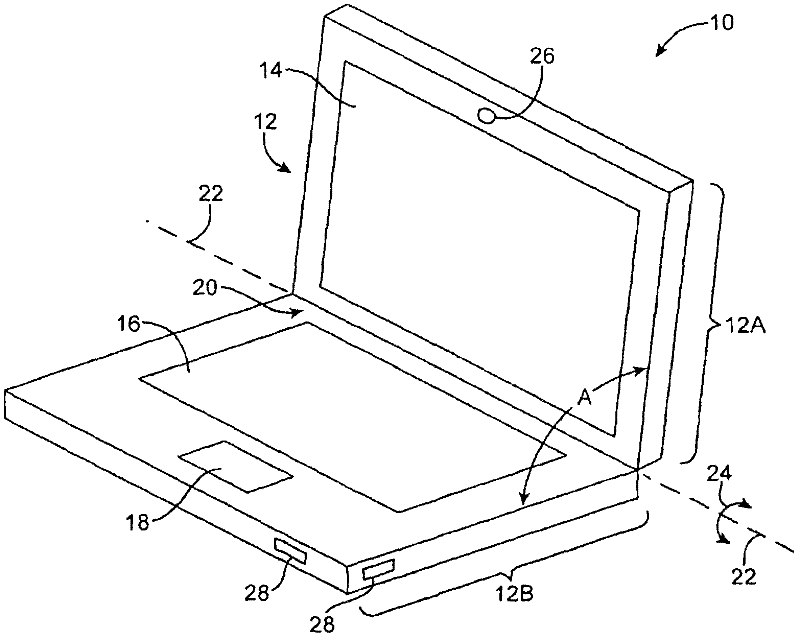
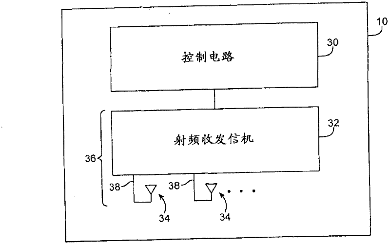
[0045] such as figure 1 An electronic device such as electronic device 10 may include wireless circuitry. For example, electronic device 10 may include wireless communication circuitry that operates over a long-range communication band, such as a cellular telephone band, and over a short-range communication band, such as at 2.4 GHz Band and 2.4GHz and 5GHz Wireless circuits that operate on the WLAN band (sometimes called the IEEE 802.11 band).

[0046] Device 10 may be a handheld electronic device, such as a cellular telephone, media player, gaming device, or other device, may be a laptop, tablet, or other portable computer, may be a desktop computer, may be a television or set-top box, or may be other Electronic equipment. Configurations are sometimes described herein as examples in which device 10 would have a rotatable cover as in a portable computer. However, this configuration is merely illustrative. Device 10 may be any suitable electronic device.

[0047] Such a...


PUM


Abstract

Electronic devices (10) may include radio-frequency transceiver circuitry (32) and antenna structures (34). The antenna structures (34) may include antenna resonating elements (60) such as dual-band antenna resonating elements that resonate in first and second communications bands. The antenna structures may also contain parasitic antenna elements (60) such as elements that are operative in only the first or second communications band and elements that are operative in both the first and second communications bands. The antenna resonating elements and parasitic elements may be mounted on a common dielectric carrier. The dielectric carrier may be mounted within a slot (56) or other opening in a conductive element. The conductive element may be formed from conductive housing structures in an electronic device such as a portable computer. The portable computer may have a clutch barrel (54) with a dielectric cover. The dielectric cover may overlap and cover the slot and the dielectric carrier.

Description

technical field [0001] The present disclosure relates to wireless electronic devices, and more particularly, to antenna structures for wireless electronic devices. Background technique [0002] Electronic devices such as computers and handheld electronic devices are often equipped with wireless communication capabilities. For example, an electronic device may use cellular telephone circuitry to communicate using cellular telephone bands. Electronic devices may use short-range wireless communication links to handle communications with nearby devices. For example, electronic devices can use 2.4GHz and 5GHz (IEEE 802.11) band and at 2.4GHz band for communication. [0003] To meet consumer demands for small form factor wireless devices, manufacturers are constantly striving to implement wireless communication circuits, such as antenna assemblies, that employ compact structures. For example, antennas have been mounted in clutch barrel portions of portable computer housings...

Claims


Application Information

Patent Timeline
Patent Type & Authority Applications(China)
IPC IPC(8): H01Q1/36H01Q1/22H01Q5/10H01Q5/357H01Q5/378
CPCH01Q5/0051H01Q1/2266H01Q1/521H01Q5/0062H01Q5/357H01Q5/378H01Q1/24H01Q5/00H04B7/24
Inventor J·古特曼胥浩D·B·基奥E·L·卡马乔M·帕斯科林尼R·W·斯科卢巴R·卡巴勒罗
Owner APPLE INC
Why Eureka
Try Eureka