Socket

A socket and pin board technology, used in coupling devices, instruments, discharge lamps, etc., to achieve the effect of expanding the pressing area and reducing scratches and damages

Active Publication Date: 2012-07-04
LTI控股公司
View PDF8 Cites 5 Cited by
  • Summary
  • Abstract
  • Description
  • Claims
  • Application Information

AI Technical Summary

Problems solved by technology

However, since the width of the latch plate is limited by the width of the latch components, there is a problem in obtaining a large area for pressing IC packages, especially large-sized IC chips.

Method used


Image

  • Socket
  • Socket
  • Socket

Examples


Embodiment Construction

[0041] The socket according to the invention is preferably realized as a test socket and is described in detail below with reference to the accompanying drawings. It should be noted that the scales given in the drawings are for the convenience of understanding the present invention and do not represent the actual scale of the product.

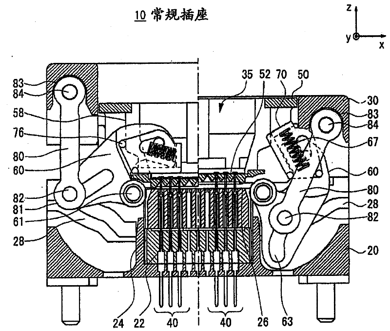
[0042] Figure 8 is a top view of an exemplary socket according to an embodiment of the present invention. The socket 100 according to the embodiment has a Figure 1 to Figure 7 The conventional socket 10 described in is substantially the same structure, but the socket 100 includes a redesigned pin plate 200 . In this embodiment, the latch plate 200 is rotatably connected to the adapter or mounting member 50A for alignment with the latch member 60 as described below. This allows the pin plate 200 to press uniformly over the entire top surface of the semiconductor device (eg, BGA package), which is particularly effective for large and / or thin...


PUM


Abstract

The invention relates to a socket. A socket (100) of the present invention includes a base member (20), a cover member (30), a plurality of contacts (40), a latch member (60A) that is rotatably supported by the base member (20) and rotates in response to movement of the cover member (30), an adaptor (50) providing a mounting surface for an IC package and attached with the base member (20) so as to move in an up and down direction in response to the movement of the cover member (30), and a latch plate (200) rotatably attached with the adaptor (50A) and urged by an elastic member. The adaptor (50A) is formed with a latch guide (58) that moves the latch plate (200) in the vertical direction when the latch plate (200) presses the IC package.

Description

technical field [0001] The present invention relates to a socket for a semiconductor device, and more particularly to a socket for a semiconductor device in which terminals are arranged in a two-dimensional array such as a BGA (Ball Grid Array) package and an LGA (Land Grid Array) package piece of socket. Background technique [0002] Semiconductor devices such as BGA and LGA packages are subjected to a burn-in test before shipment, which applies stress due to high temperature to the semiconductor device. This excludes in advance components that will fail within a certain period of time after shipment. Sockets used for burn-in testing are generally of two types. One is a top-opening socket whose cover element is vertically reciprocating. The other is a shell-type socket whose cover element is rotary. As for the open top type socket, Japanese Patent Application Publication No. 2009-140629, that is, U.S. Patent Application Publication No. 2010-0248518A1 (Patent Document 1)...

Claims


Application Information

Patent Timeline
Patent Type & Authority Applications(China)
IPC IPC(8): H01R13/639H01R13/502H01R33/74
CPCG01R1/0441H01R33/76
Inventor 高桥英行佐野秀纪
Owner LTI控股公司
Why Eureka
Try Eureka