Transmitting device

A transmitting device and a technology for transmitting signals, which are applied in the directions of amplifier combination, power amplifier, etc., can solve the problems of large margin of the transmitting device, the number of working hours, the increase of the cost, the increase of the cost, etc.

Inactive Publication Date: 2015-06-03
KK TOSHIBA
View PDF5 Cites 0 Cited by
  • Summary
  • Abstract
  • Description
  • Claims
  • Application Information

AI Technical Summary

Problems solved by technology

In order to suppress the unevenness of input power and gain, it will lead to an increase in man-hours and costs
On the other hand, if the performance of each power amplifier is allowed to vary, the transmission device as a whole will become a system with a large margin, and the cost will still increase.

Method used


Image

  • Transmitting device
  • Transmitting device
  • Transmitting device

Examples


Embodiment Construction

[0012] (Structure of the embodiment)

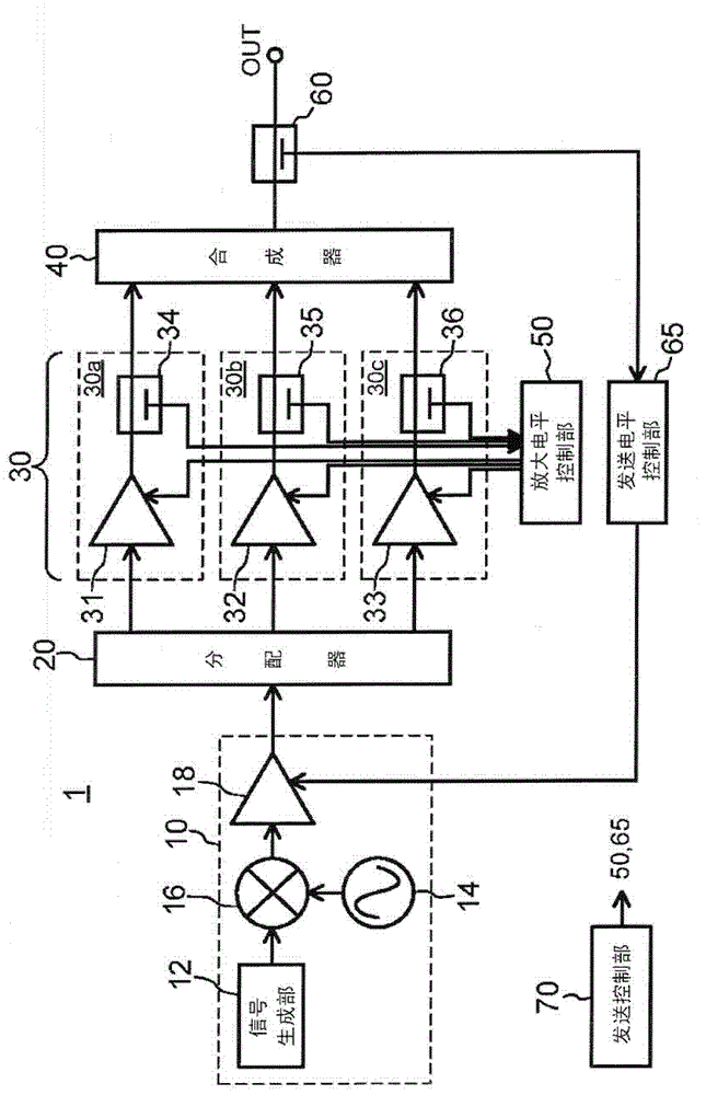
[0013] Hereinafter, an embodiment will be described in detail with reference to the drawings. Such as figure 1 As shown, the transmission device 1 of this embodiment has an exciter 10 , a distributor 20 , a power amplification unit 30 and a combiner 40 .

[0014] The exciter 10 generates a first amplified signal modulated in a prescribed manner and converted into a prescribed transmission frequency. exist figure 1 In the example shown, the driver 10 has a signal generator 12 , a local oscillator 14 , a mixer 16 and a driver amplifier 18 . The signal generating unit 12 generates a baseband signal obtained by modulating voice, data, or the like in a predetermined manner. The local oscillation unit 14 generates a local signal for converting the baseband signal into a predetermined transmission frequency. The mixer 16 converts the baseband signal into a transmission signal of a predetermined transmission frequency using the local signal....


PUM


Abstract

A transmitting device comprises: an exciting amplifier used for amplifying a transmitting signal and outputting a first amplifying signal; a divider used for dividing the first amplifying signal into a plurality of divided signals; a plurality of power amplifiers used for respectively amplifying the divided plurality of divided signals and outputting second amplifying signals; and a synthesizer used for synthetizing the plurality of second amplifying signals output by the plurality of power amplifiers and outputting a synthetized signal; a plurality of power detection units used for respectively detecting the plurality of second amplifying signals output by the plurality of power amplifiers; an amplifying level control unit used for controlling the plurality of power amplifiers based on detected results of the plurality of power detection units and making the power of the second amplifying signals output by the plurality of power amplifiers consistent; a transmitting signal detection unit used for detecting at least one side of the power of the synthetized signal or distortion composition; and a transmitting level controller used for controlling the exciting amplifier based on the detected result of the transmitting signal detection unit and making the power of the synthetized signal into a first level and making amount of the distortion composition of the synthetized signal below a second level.

Description

[0001] CROSS-REFERENCE TO RELATED APPLICATIONS: This application is based on Japanese Patent Application No. 2010-290514 (filing date: December 27, 2010), and enjoys the priority of this application. This application incorporates the entire contents of this application by reference thereto. technical field [0002] Embodiments of the present invention relate to a sending device. Background technique [0003] For example, a transmitting device used in broadcast equipment connects a plurality of power amplifiers in parallel to combine the outputs of the plurality of power amplifiers in order to generate a relatively high-power transmission signal. In this case, the output power of each power amplifier is preferably equal to each other. However, in practice, the output power of each power amplifier varies due to the variation in input power or gain of each power amplifier. Therefore, the rated maximum power of the power amplifiers connected in parallel and operating is design...

Claims


Application Information

Patent Timeline
Patent Type & Authority Patents(China)
IPC IPC(8): H03F3/20H03F3/68
Inventor 大塚国明
Owner KK TOSHIBA
Why Eureka
Try Eureka