Ultrasonic imaging method and device

An ultrasonic imaging method and imaging technology, applied in blood flow measurement devices, ultrasonic/sonic/infrasonic diagnosis, sound wave diagnosis, etc., can solve the problems of scanning time compression, poor time resolution, image mismatch, etc., and achieve quality assurance Effect

Active Publication Date: 2012-07-11
SHENZHEN MINDRAY BIO MEDICAL ELECTRONICS CO LTD
View PDF10 Cites 33 Cited by
  • Summary
  • Abstract
  • Description
  • Claims
  • Application Information

AI Technical Summary

Problems solved by technology

In the triplex imaging mode, when performing three different imaging on the same position, it is necessary to use different types of pulses, including B pulse, C pulse and D pulse, to scan the position in time division, and the tissues and organs of the human body are time-sharing. When changing, time-sharing scanning at the same position will cause image mismatch, so the scanning time occupied by each scanning is limited
If you want to have higher spectral quality, you must los

Method used


Image

  • Ultrasonic imaging method and device
  • Ultrasonic imaging method and device
  • Ultrasonic imaging method and device

Examples


Embodiment 1

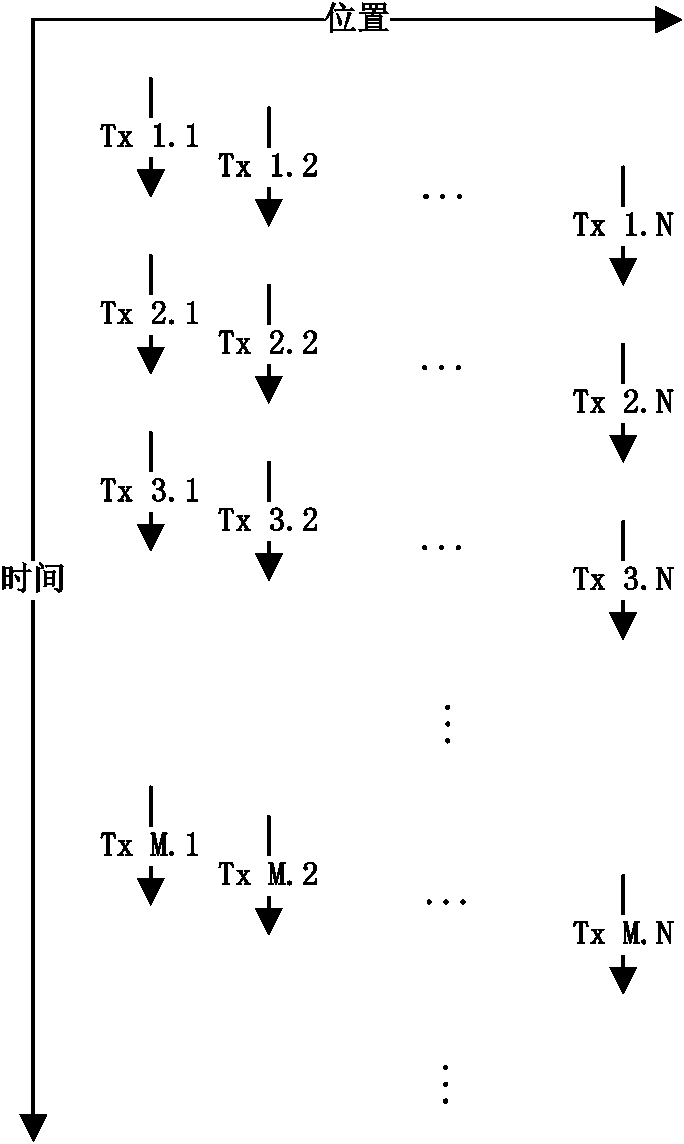
[0038] In this embodiment, only Doppler pulses are emitted, and Doppler pulses can be used to generate two-dimensional images, blood flow images and spectrum images, and the transducer emits Doppler pulses for Doppler scanning; the transducer The received echo signal is a Doppler pulse echo signal. Such as figure 2 As shown, Tx1.1 to Tx1.N constitute a complete Doppler pulse scanning frame; Tx1.1 to TxM.1 constitute a spectrum calculation package; the frequency of Tx1.1 to Tx2.1 is the pulse repetition frequency ( PRF, Pulse Repetition Frequency), which determines the maximum measurable velocity, from which the Doppler information of a scan line can be calculated. In the imaging step 200, the two-dimensional image processing step, the blood flow image processing step and the spectral image processing step are performed in parallel, that is, all scan lines (ie, from 1 to N) are combined to reconstruct the The two-dimensional image of each scan line (such as Tx1. 2 to TxM.2)...

Embodiment 2

[0040] The difference between this embodiment and the first embodiment is that the transmitted pulses are Doppler pulses and B pulses, and the pulse transmission sequence is: B pulses are transmitted between two adjacent frames of Doppler scans. Doppler pulses can be used to generate two-dimensional images, blood flow images, and spectrum images, while B pulses can be used to generate two-dimensional images; the transducer uses Doppler pulses for Doppler scanning, and B pulses for B-line Scanning; the echo signals received by the transducer are Doppler pulse echo signals and B pulse echo signals.

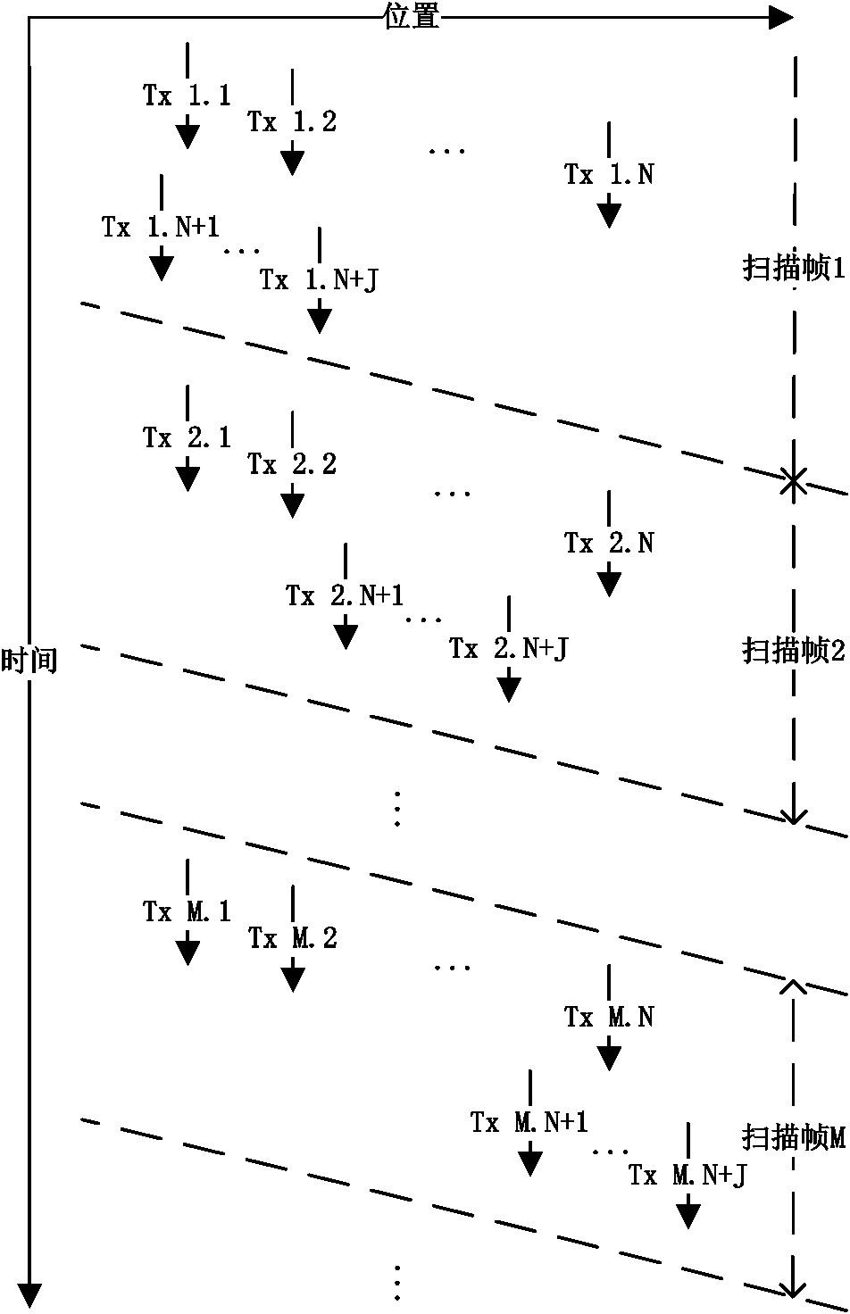
[0041] Such as image 3 As shown, the Doppler pulse scan is from Tx1.1 to TxM.N, which is the same as the case of only Doppler pulse scan described in Embodiment 1, and J times are added in the scanning gap from Tx1.N to Tx2.1 The B-line scan is Tx1.N+1 to Tx1.N+J, and the scan position can be the same as that of the Doppler pulse scan, or it can be different. That is to say, the ...

Embodiment 3

[0044] The difference between this embodiment and Embodiment 2 is that although the transmitted pulses are Doppler pulses and B pulses, the pulse transmission sequence is: B pulses are transmitted between two adjacent Doppler scan data packets, One of the Doppler scan packets contains several frames of Doppler scans. Doppler pulses can be used to generate two-dimensional images, blood flow images, and spectrum images, while B pulses can be used to generate two-dimensional images; the transducer uses Doppler pulses for Doppler scanning, and B pulses for B-line Scanning; the echo signals received by the transducer are Doppler pulse echo signals and B pulse echo signals.

[0045] Such as Figure 4 As shown, the difference between this embodiment and the second embodiment is that the scanning gap between two adjacent frames from Tx1. A B-line scan frame is inserted between two adjacent Doppler pulse scan data packets, each frame contains J transmissions, and its scan position ca...


PUM


Abstract

The invention discloses an ultrasonic imaging method and a device. The method comprises a transmitting and receiving step, an echo signal processing step and a displaying step. In the transmitting and receiving step, Doppler pulses are transmitted to an object to be detected, Doppler scanning is carried out by the aid of the Doppler pulses, and echo signals are received from the object to be detected and are Doppler pulse echo signals; in the echo signal processing step, the echo signals are processed and outputted, the echo signal processing step comprises an imaging step, and the imaging step comprises a parallelly processed two-dimensional image processing step, a blood flow image processing step and a frequency spectrum image processing step; and in the displaying step, output of the echo signal processing step is displayed. A two-dimensional image, a blood flow image and a frequency spectrum image are generated in parallel by means of adopting identical scanning signals; and in an implementation mode, one or a plurality of sampling doors is arranged in the received echo signals, and frequency spectrum image signals corresponding to the sampling doors can be simultaneously obtained.

Description

technical field [0001] The present invention relates to ultrasonic imaging, in particular to an ultrasonic imaging method and device. Background technique [0002] Medical ultrasound equipment generally includes modules such as transducers (or probes), transmitting / receiving circuits, and digital signal processing. Among them, the transducer is composed of multiple array elements, and each array element has an electrical signal and an acoustic signal. Convert function. Driven by the transmitting circuit, each array element in the transducer converts electrical signals into ultrasonic waves and transmits them to human tissues. When ultrasonic waves are transmitted in human tissue, phenomena such as absorption, reflection, refraction, and scattering will occur. Part of the scattered signal will return to the transducer and be converted into an analog electrical signal again. The receiving circuit converts these received analog electrical signals into digital signals. Then t...

Claims


Application Information

Patent Timeline
IPC IPC(8): A61B8/00A61B8/06
CPCA61B8/488A61B8/06A61B8/5246A61B8/5207A61B8/0891
Inventor 马忠伟姚林鑫
Owner SHENZHEN MINDRAY BIO MEDICAL ELECTRONICS CO LTD
Why Eureka
Try Eureka