Method and manufacturing equipment for winding forming of snap rings

A type of machine and spiral type technology, applied in the field of metal machining without cutting, can solve the problems of high cost, many corner scraps, and large consumption, so as to shorten the product process, prolong the service life, and increase the flexibility. Effect

Inactive Publication Date: 2012-07-11
浙江鑫永利卡环有限公司
View PDF6 Cites 7 Cited by
  • Summary
  • Abstract
  • Description
  • Claims
  • Application Information

AI Technical Summary

Problems solved by technology

[0002] Snap rings are necessary parts commonly used in mechanical equipment, and they are used in a large amount. The snap rings in the prior art are usually stamped out of steel plates, and there are too many corner scraps, and it is di

Method used


Image

  • Method and manufacturing equipment for winding forming of snap rings
  • Method and manufacturing equipment for winding forming of snap rings
  • Method and manufacturing equipment for winding forming of snap rings

Examples


Embodiment Construction

[0022]

[0023] The present invention will be further elaborated below by means of the accompanying drawings and examples.

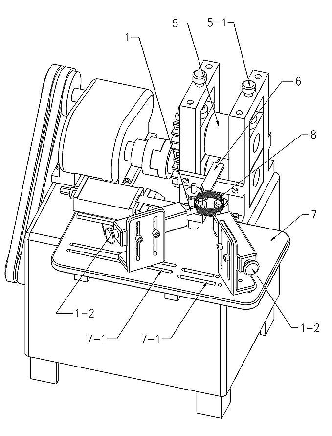
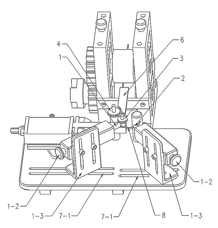
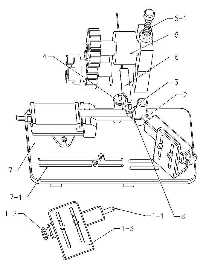
[0024] The structure of the card surround molding machine is as follows Figure 1 to Figure 3 As shown, it mainly includes a first ejector rod 1, a second ejector rod 2, a center roller 3, a large roller 4, a roller 5, a wire guide 6, and a frame panel 7.

[0025] The rollers 4 are installed in pairs up and down, and the upper roller is equipped with an adjusting screw 5-1, which can adjust the gap between the upper and lower rollers according to the thickness of the flat steel strip 8 required;

[0026] In the middle of the wire guide 6, there is a channel for a flat steel belt 8, and channels of various sizes can be set according to the serialization requirements;

[0027] An annular groove 3-1 adapted to the thickness and shape of the flat steel strip 8 is provided on the circumference profile of the center roller 3 and the large roller 4, and its f...


PUM


Abstract

The invention discloses method and manufacturing equipment for winding forming of snap rings. The method comprises the following steps: rolling a steel wire flat, spirally bending the flat steel strip, tempering and shaping, cutting circles one by one, adjusting diameter to the preset value, cutting according to the designed shape and grounding. A snap ring winding forming machine for spirally bending the flat steel strip is also disclosed. The steel wire clamped between the rollers which rotate oppositely is rolled to the flat steel strip and is forced to be discharged through the rollers; the flat steel strip is pushed by the groove of a first ejector rod to change the advance direction and continue to advance after bending, and the flat steel strip is pushed by the groove of a second ejector rod to change the advance direction again; based on the principle that a circle is defined by three points, the flat steel strip is bended to a spiral coil of the preset diameter under the combination action of a large roller and the two first ejectors; and after tempering and shaping, each circle of the spiral coil is cut off and then cut and notched to obtain snap ring final products. The invention has the benefits that the large-tonnage punch press is not needed during process, no edge scrap or waste is produced during the manufacturing process, the steel utilization rate is increased, and the process flow of products is shortened.

Description

technical field [0001] The invention relates to the field of non-cutting metal machining, in particular to a method and manufacturing equipment for ring forming of clips, which are suitable for manufacturing snap rings, which are general parts such as automobile gearboxes and wind power equipment. Background technique [0002] Snap rings are necessary parts commonly used in mechanical equipment, and they are used in a large amount. The snap rings in the prior art are usually stamped out of steel plates, and there are too many corner scraps, and it is difficult to complete the snap rings with a diameter of 200 mm or more. 500 tons The above precision punching machines are not currently available in China, and even if they are available, the cost of manufacturing snap rings must remain high. In view of this, the inventor has done in-depth research on the manufacturing materials of snap rings, broke through the traditional thinking, used flattened steel wires to wind and form,...

Claims


Application Information

Patent Timeline
IPC IPC(8): B21F37/00
Inventor 陈岳忠朱菊萍俞立安
Owner 浙江鑫永利卡环有限公司
Why Eureka
Try Eureka