
Submersed nozzle for continuous casting moulds

A continuous casting crystallizer and immersion technology, which is applied in the direction of casting molten material container, casting equipment, metal processing equipment, etc., can solve the problem of not being able to alleviate mold slag agglomeration and corner cracks, and it is difficult to greatly reduce stream damage, etc. problems, to achieve the effect of improving the continuous casting process, improving the quality of the slab, and reducing the effect of cold steel

Inactive Publication Date: 2012-07-11
WISDRI ENG & RES INC LTD
View PDF6 Cites 0 Cited by
  • Summary
  • Abstract
  • Description
  • Claims
  • Application Information

AI Technical Summary

Problems solved by technology

This kind of submerged nozzle can improve the flow state of molten steel, and can also appropriately reduce the impact of molten steel on the solidified shell in the middle of the mold. Can not alleviate a series of problems such as cold steel, mold slag agglomeration and corner cracks caused by overcooling at the corner of the crystallizer

Method used


Image

  • Submersed nozzle for continuous casting moulds
  • Submersed nozzle for continuous casting moulds
  • Submersed nozzle for continuous casting moulds

Examples


Embodiment 1

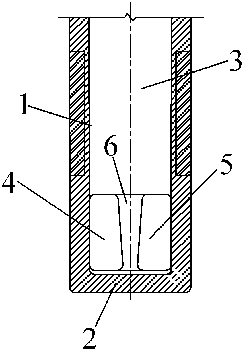
[0030] When pouring the slab, you can use such as Image 6 The shown two-sided four-hole submerged nozzle is used for pouring, and the cross-sections of the submerged water side wall 1 and the inner cavity 3 are both flat with front and rear planes and left and right arc surfaces. The bottom 2 of the submerged nozzle is set in a concave shape, the inclination angle of the upper and lower walls of the first side hole 4 and the second side hole 5 is -15°, the inclination angle of the outer wall surface is 20°, and the side holes are chamfered square, The chamfer radius is 10mm. The width of the spacer 6 between the holes on both sides is 15mm. During pouring, the spacer 6 is aligned with the center of the narrow surface of the slab crystallizer 7, and the molten steel enters from the upper opening of the inner cavity 3 and flows out from the first side hole 4 and the second side hole 5, which can reduce the temperature of the high temperature molten steel. The impact on the ce...

Embodiment 2

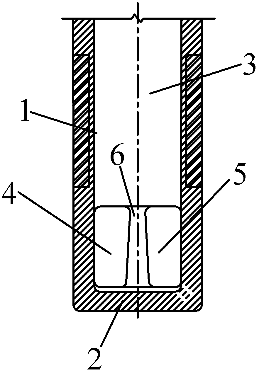
[0032] When pouring blooms, such as Figure 7The shown two-sided four-hole submerged nozzle is poured, and the cross-section of the submerged water side wall 1 and the inner cavity 3 is circular. The bottom 2 of the submerged nozzle is set in a concave shape, the inclination angle of the upper and lower walls of the first side hole 4 and the second side hole 5 is -10°, the inclination angle of the outer wall surface is 30°, and the side holes are chamfered square, The chamfer radius is 10mm. The width of the spacer 6 between the holes on both sides is 15 mm. When pouring, the spacer 6 is aligned with the center of the narrow surface of the bloom mold 8, and the molten steel enters from the upper opening of the inner cavity 3 and flows out from the first side hole 4 and the second side hole 5, which can reduce the temperature of the high temperature molten steel. The impact on the thinner billet shell in the center of the narrow face, and the temperature compensation for the ...


PUM


Abstract

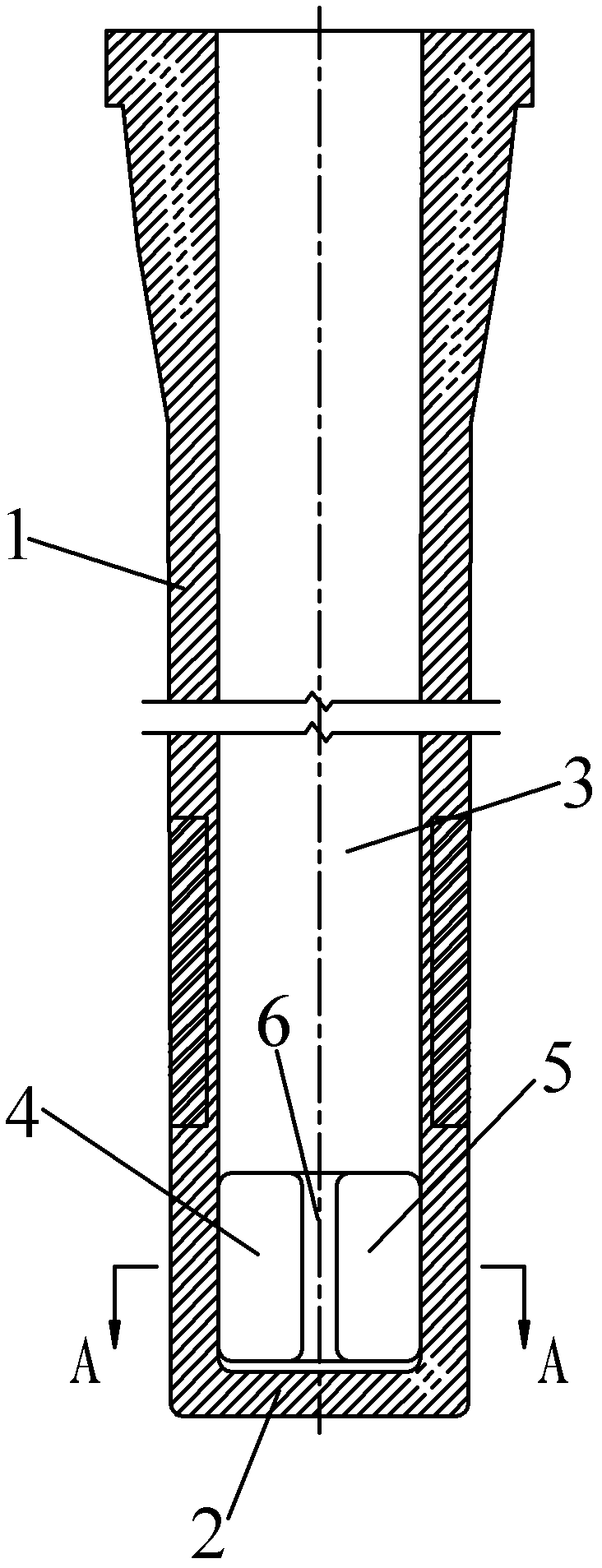
The invention relates to a submersed nozzle for continuous casting moulds. The submersed nozzle comprises side walls and a bottom, wherein two symmetrical side walls on a narrow surface of a continuous casting mould are respectively provided with two side holes; the side holes in the opposite side walls are same in size and shape and axially symmetrical about the central axis of the nozzle; two side holes in a same side wall are same in size and shape, separated from ach other by a vertical separating block connected with the side wall and the bottom, and axially symmetrical about a central line of the upper and lower edges of the separating block; and two side faces (close to the middle separating block) of two side holes in the vertical direction, namely, inside wall surfaces, are flat surfaces parallel to the central line of an inner cavity, and the other two separated side faces, namely, outside wall surfaces, are inclined surfaces which extend outwards from the inside to the outside. The separating block prevents high-temperature liquid steel from flowing to high temperature areas in the middle parts of the wall surfaces, and divergence angles of the outside wall surfaces of the side holes guide the liquid steel to flow to corner areas with lower temperature, thereby ensuring the uniformity of temperature and composition of the horizontal liquid steel.

Description

technical field [0001] The invention relates to a continuous casting crystallizer for steel, in particular to a submerged nozzle device for continuous casting crystallizers for slabs and blooms (referring to square billets with cross-sectional dimensions larger than 200mm×200mm). Background technique [0002] Under the existing technology, the slab continuous casting crystallizer mainly adopts double-side hole submerged nozzles for pouring, and the bloom (referring to the billet whose cross-sectional size is larger than 200mm×200mm) continuous casting crystallizer can use straight-through nozzles according to different casting requirements , double-side hole nozzles and four-side hole nozzles for pouring. The main structure of the submerged nozzle with double-sided holes used in the current slab and bloom crystallizers is basically the same. They are all tubes with closed bottom ends pressed by refractory materials, including a vertical inner cavity with an upper opening and...

Claims


Application Information

Patent Timeline
Patent Type & Authority Applications(China)
IPC IPC(8): B22D41/50
Inventor 徐海伦潘国友邵远敬马春武幸伟徐永斌叶理德
Owner WISDRI ENG & RES INC LTD
Learn More