Powder metallurgy forming mold carrier with two point five or three point five lower palates

A technology of powder metallurgy and 2.5, which is applied in the field of powder forming hydraulic machine formwork, which can solve the problems of unfavorable market competition, time-consuming, and increased material consumption, and achieve the effects of improving market competitiveness, reducing production costs, and simple mold structure

Inactive Publication Date: 2012-07-11
南通富仕液压机床有限公司
View PDF5 Cites 20 Cited by
  • Summary
  • Abstract
  • Description
  • Claims
  • Application Information

AI Technical Summary

Problems solved by technology

The disadvantages of the current powder metallurgy molding formwork are: when forming inner stepped structural parts, the mold and The accessories of the mold are complicated, the production cost is high, and the accuracy is difficult to guarantee. Some inner stepped structural parts cannot be formed on the mold base of this structure; when supporting the female mold with stepped cavity, use Small hydraulic cylinder in the horizontal direction, the end of the small hydraulic cylinder is connected with a limit block, when pressed, the small hydraulic cylinder is ejected, and the end limit block is pressed against the small fixed plate below to act as a fixed limit to achieve support, and the support force is relatively large. Poor, the quality of the pressed product is unstable; the feeding limit of the floating plate is realized by setting the limit nut at the end of the piston rod of the floating cylinder. When adjusting, the limit nut needs to be manually rotated. Repeated adjustments lead to low efficiency; when pressing products with high outer steps and heights, it is necessary to incr

Method used


Image

  • Powder metallurgy forming mold carrier with two point five or three point five lower palates
  • Powder metallurgy forming mold carrier with two point five or three point five lower palates
  • Powder metallurgy forming mold carrier with two point five or three point five lower palates

Examples


Embodiment Construction

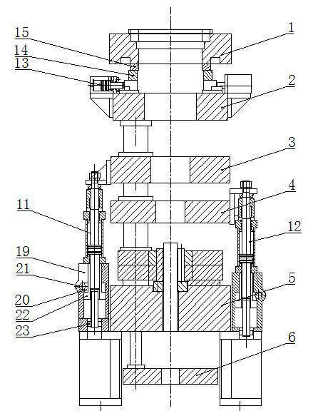
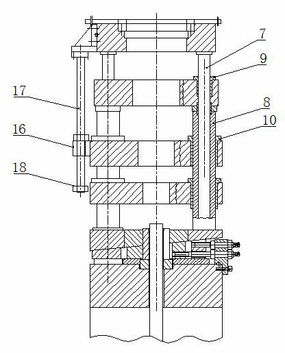
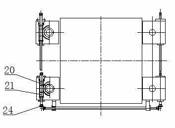
[0015] Such as figure 1 , 2 As shown, the lower formwork includes female formwork 1, upper fixed plate 2, floating plate I3, floating plate II4, lower fixed plate 5, lower formwork 6, lower guide column 7, support column 8, guide sleeve I9, guide sleeve II10, Floating cylinder 11, floating cylinder 12, side oil cylinder 13, block II14, block I15, limit seat 16, pull-off rod 17, limit nut I18, worm gear box 19, worm gear 20, worm 21, external thread adjustment Screw rod 22, limit nut II 23.

[0016] Above-mentioned lower formwork is provided with female template 1, upper fixed plate 2, floating plate, lower fixed plate 5 and lower template 6 successively from top to bottom, and floating plate has at least one layer. The lower 2.5 formwork adopts a female template, a floating plate and an upper fixed plate. The lower 3.5 formwork adopts a negative template, two floating plates and an upper fixed plate, and so on.

[0017] In the present embodiment, the lower formwork is a l...


PUM


Abstract

The invention relates to a powder metallurgy forming mold carrier with two point five or three point five lower palates, which is characterized in that a lower framework comprises a female mold plate, an upper fixing plate, floating plate, a lower fixing plate and a lower mold plate, wherein four corners of the female mold plate are fixedly connected with the lower mold plate by lower guide columns, four corners of the upper fixing plate and four corners of the lower fixing plate are fixedly connected by support columns, the floating plate is driven by a floating cylinder, a female mold step forming structure or product shaping-supporting structure is arranged between the female mold and the upper fixing plate, a pulling rod mechanism is arranged between the female mold plate and the floating plate, and a floating material stamping and adding fine-adjustment mechanism is arranged on the floating plate. The powder metallurgy forming mold carrier has the advantage of being capable of realizing two functions of inner and outer step forming and shaping of multi-stepped products; in addition, the powder metallurgy forming framework can finish pressing of a multi-stepped metal product at one time, the pressing quality is good, the pressing efficiency is high, the adjustment is convenient, the mold carrier accuracy is high, the rigidity is high and the stability is good; and a mold has a simple and reasonable structure, and is convenient to adjust.

Description

technical field [0001] The invention relates to a mold base of a powder forming hydraulic press, in particular to a 2.5 and 3.5 mold base for powder metallurgy molding. Background technique [0002] The powder metallurgy forming mold base is the frame for installing the powder metallurgy mold, which is used to connect with the press, transmit pressure and various actions, and make the main parts of the mold complete the powder forming requirements. The traditional powder metallurgy molding formwork is mainly composed of female mold support plate, die punch support plate, mandrel support plate and other templates, plus guide pillars, guide sleeves, tie rods, etc. Three, up two down two, up two down three and so on. The disadvantages of the current powder metallurgy molding formwork are: when forming inner stepped structural parts, the mold and The accessories of the mold are complicated, the production cost is high, and the accuracy is difficult to guarantee. Some inner ste...

Claims


Application Information

Patent Timeline
IPC IPC(8): B22F3/03B22F3/04
Inventor 许桂生
Owner 南通富仕液压机床有限公司
Why Eureka
Try Eureka