Turbine blade assembling insurance clamp and method for performing impeller clamping thereof

A technology of turbine blades and fixtures, applied in hand-held tools, manufacturing tools, workpiece clamping devices, etc., can solve the problems of affecting the repair progress, waste of lock pieces, time-consuming and laborious, etc., to improve the repair progress, improve the qualification rate, reduce the The effect of labor intensity

Active Publication Date: 2014-07-16
SICHUAN YAMEI POWER TECH
View PDF5 Cites 0 Cited by
  • Summary
  • Abstract
  • Description
  • Claims
  • Application Information

AI Technical Summary

Problems solved by technology

Time-consuming and labor-intensive, seriously affecting the repair progress, and wasting a lot of locking pieces, which virtually increases the cost

Method used


Image

  • Turbine blade assembling insurance clamp and method for performing impeller clamping thereof
  • Turbine blade assembling insurance clamp and method for performing impeller clamping thereof
  • Turbine blade assembling insurance clamp and method for performing impeller clamping thereof

Examples


Embodiment Construction

[0031] All features disclosed in this specification, or steps in all methods or processes disclosed, may be combined in any manner, except for mutually exclusive features and / or steps.

[0032] Any feature disclosed in this specification (including any appended claims, abstract and drawings), unless expressly stated otherwise, may be replaced by alternative features which are equivalent or serve a similar purpose. That is, unless expressly stated otherwise, each feature is one example only of a series of equivalent or similar features.

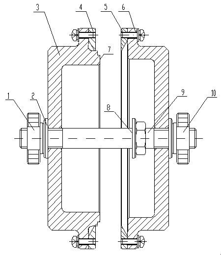
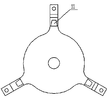
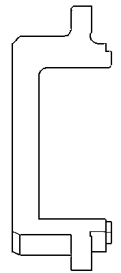
[0033] Such as Figure 4 As shown, it is the impeller structure that needs to be insured; Figure 1 to Figure 3 It is a structural schematic diagram of a safety fixture for assembling turbine blades according to the present invention. Taking the above four drawings as examples, the fixture and its clamping method are described. In the present invention, withfigure 1 For example, the inner end surface of the positioning seat 3 on the intake s...


PUM


Abstract

The invention discloses a turbine blade assembling insurance clamp and a method for performing impeller clamping thereof, which belong to the technical field of aircraft engine gas turbine blade assembling. Bosses are evenly distributed on the edge portion of an air inlet edge positioning seat of a turbine disc of the turbine blade assembling insurance clamp, a screw penetrates through the air inlet edge positioning seat of the turbine disc to be fixed with an air discharging edge positioning seat of the turbine disc, and in use, turbine blades are fixed. The method for performing impeller clamping includes the following steps: step 1 assembling the air inlet edge positioning seat and an impeller; step 2 installing the impeller in an air inlet edge positioning seat assembly; step 3 installing a gasket; and step 4 installing an air discharging edge positioning seat assembly. The turbine blade assembling insurance clamp leads insured blades to meet requirements for dimensions of 3.4+ / -0.5mm, avoids the blades from being ejected to be loose and improves turbine blade assembling yield rate. The method for performing blade clamping can perform turbine positioning fast and conveniently and reduces labor intensity and maintenance cost.

Description

technical field [0001] The invention relates to an assembly technology of an aero-engine gas turbine blade, in particular to an assembly technology in which a turbine disk and blades are connected by locking pieces. Background technique [0002] The turbine disk and blades connected by the locking plate, the acceptance criteria for the assembly of the turbine blades are: no looseness is allowed after the blades are secured, and the boss on the leading edge of the blade is 3.4±0.05mm higher than the end surface of the turbine disk inlet side. In the process of assembling the insurance of the engine turbine blades, due to the design defects of the original assembly tooling, the blades that have been insured are often loosened by the tooling, making the blades loose, and cannot meet the size requirement of 3.4±0.05mm. Therefore, it is necessary to remove and discard the lock plate, and to insure the blades again so that all the blades on the entire turbine disk meet the size re...

Claims


Application Information

Patent Timeline
Patent Type & Authority Patents(China)
IPC IPC(8): B25B11/02B25B27/00
Inventor 刘雅楣王睿
Owner SICHUAN YAMEI POWER TECH
Why Eureka
Try Eureka