
Die cooling structure and die

A mold cooling and modeling technology, applied in the field of molds, can solve problems such as uneven cooling, and achieve the effect of increasing the effective cooling area, improving product quality, and shortening product molding cycle.

Active Publication Date: 2012-07-11
DONGGUAN HAOSHUN PRECISION TECH CO LTD
View PDF7 Cites 8 Cited by
  • Summary
  • Abstract
  • Description
  • Claims
  • Application Information

AI Technical Summary

Problems solved by technology

[0003] The main purpose of the present invention is to provide a mold cooling structure, which aims to solve the above-mentioned technical problems of uneven cooling of uneven products, shorten the injection molding cycle, reduce injection molding costs, and improve production efficiency

Method used


Image

  • Die cooling structure and die
  • Die cooling structure and die
  • Die cooling structure and die

Examples


Embodiment Construction

[0023] It should be understood that the specific embodiments described here are only used to explain the present invention, not to limit the present invention.

[0024] The embodiment of the present invention discloses a mold cooling structure, and also discloses a mold including the mold cooling structure. For convenience of description, the mold cooling structure will be described below in conjunction with the mold.

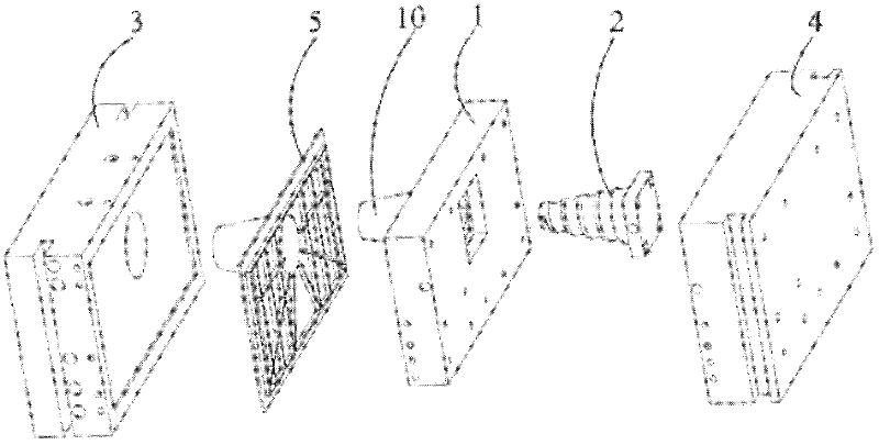
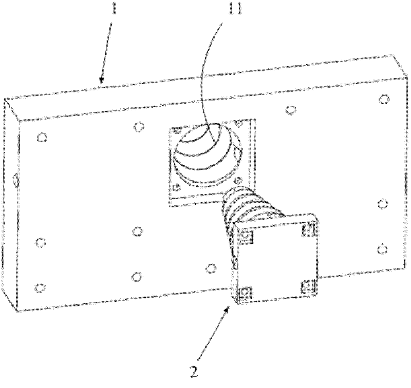
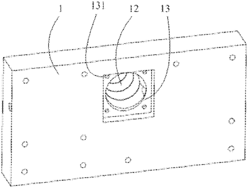
[0025] Such as figure 1 As shown, the mold of the present invention includes a rear mold core 1 , a cooling insert 2 , a front mold 3 and a rear mold frame 4 . The rear mold core 1 comprises protrusions 10 for shaping the recesses of the product 5 . As known to those skilled in the art, the rear mold includes a rear mold core 1 and a rear mold frame 4, the rear mold core 1 is installed in the rear mold frame 4, and when the front mold 3 and the rear mold are closed, the product 5 is formed on the front mold 3 and between the rear model core 1. combine figu...


PUM


Abstract

The invention discloses a die cooling structure, which comprises a rear die core, wherein the rear die core comprises a protrusion for forming a concave part of a product; an accommodating cavity is formed in the protrusion; the die cooling structure also comprises a cooling insert inserted into the accommodating cavity; the inner surface and / or the outer surface of the cooling insert is provided with a water groove for cooling water to flow; and the core of the cooling insert is provided with a water channel. The rear die core can be quickly and uniformly cooled, phenomena that a product is bent, deformed, locally shrunk and the like due to nonuniform cooling of the rear die core are avoided, a product forming period is shortened, the injection molding cost is reduced and the product quality and production efficiency are improved.

Description

technical field [0001] The invention belongs to the field of molds, in particular to a mold cooling structure and a mold comprising the mold cooling structure. Background technique [0002] At present, the water transport structure of most injection molds adopts straight-through cooling pipes, and the straight-through cooling pipes have a better cooling effect on product structures with smooth surfaces. However, with the complexity of the product structure, for uneven products, the effect of using a straight-through cooling pipe structure is very poor. For example, the TV base mould, originally the bracket on the base and the base were molded separately, in order to save the cost of mold development, now the bracket and the base are opened together and molded together. Although the number of vertical and horizontal drilling holes on the mold has been increased, the structure of the protruding bracket cannot be uniformly cooled, resulting in a long injection molding cycle an...

Claims


Application Information

Patent Timeline
Patent Type & Authority Applications(China)
IPC IPC(8): B29C45/73
Inventor 王学敏
Owner DONGGUAN HAOSHUN PRECISION TECH CO LTD
Learn More