Defective recording element detecting apparatus and method, and image forming apparatus and method

一种记录元件、检测设备的技术,应用在电气元件、图像通信、印刷等方向,能够解决摆动或弯曲、图像读取光学系统摇摆等问题

Inactive Publication Date: 2012-07-11
FUJIFILM CORP
View PDF8 Cites 17 Cited by
  • Summary
  • Abstract
  • Description
  • Claims
  • Application Information

AI Technical Summary

Problems solved by technology

[0014] (2) Vibration of the equipment, etc. will cause the image reading optical system to wobble and cause line wobble or bending reflecting the vibration on the read image
Therefore, such non-reproducible deformation and light intensity fluctuation (shading) are fluctuation factors that are difficult to correct using a fixed correction table, etc.

Method used


Image

  • Defective recording element detecting apparatus and method, and image forming apparatus and method
  • Defective recording element detecting apparatus and method, and image forming apparatus and method
  • Defective recording element detecting apparatus and method, and image forming apparatus and method

Examples


specific Embodiment approach

[0082]

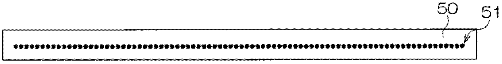
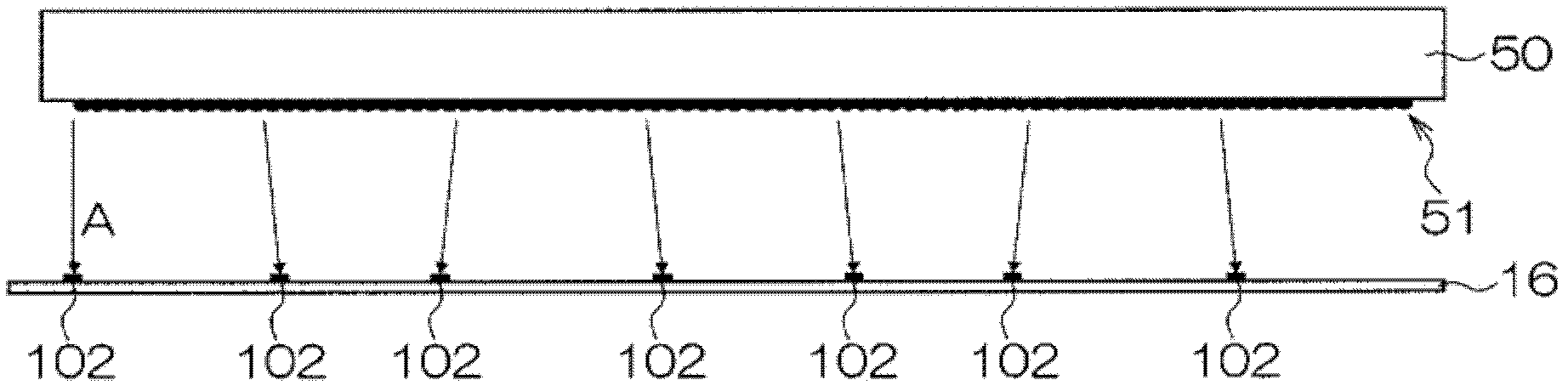
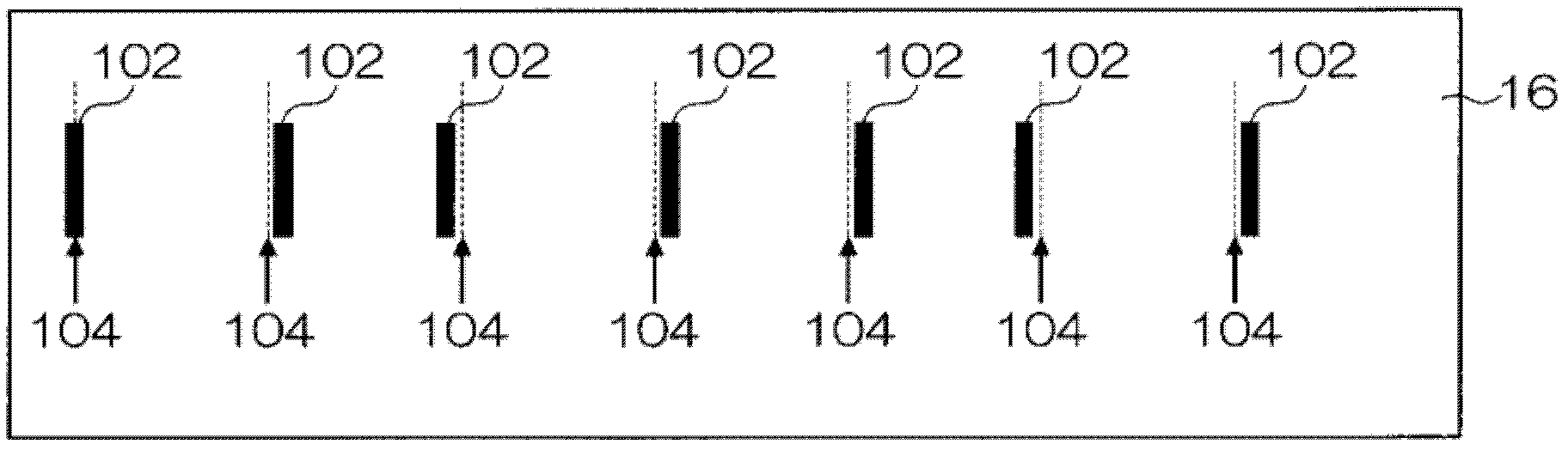
[0083] An error in an ink droplet deposition position (recording position) is introduced as an example of an error caused by a defective nozzle. Figure 1A to Figure 1C is a schematic diagram schematically illustrating a state where the deposition position of the ink droplet ejected from the nozzle deviates from the ideal deposition position on the recording medium. Figure 1A It is a plan view showing a line arrangement of a plurality of nozzles 51 in the head 50 . Figure 1B is a schematic diagram of a state in which ink droplets are ejected from nozzles 51 toward a sheet of recording medium or paper (hereinafter referred to as "recording paper") 16 viewed from the lateral direction. exist Figure 1B , arrow A schematically indicates the ejection direction of ink droplets from nozzles 51 . Figure 1C is a schematic diagram showing an example of a test pattern 102 formed on the recording paper 16 by ink droplets ejected from the nozzle 51 and deposited on the rec...


PUM


Abstract

The invention provides a defective recording element detecting apparatus and method, and an image forming apparatus and method. The defective recording element detecting apparatus includes: read image data acquiring means adapted to acquire read image data of a test pattern recorded on a recording medium by a recording head having a plurality of recording elements; reference area setting means adapted to set a reference area including a part of the test pattern on a read image; comparison area setting means adapted to set a comparison area on the read image; correlation operation means adapted to perform a correlation operation between the comparison area and the reference area while making the comparison area to conduct relative translation relative to the reference area; distortion correction value determining means adapted to determine a distortion correction value so as to correct the offset of the image in the comparison area relative to that of the reference area; image distortion correcting means adapted to correct image distortion of the read image using the distortion correction value; and defective recording element determining means adapted to identify a defective recording element according to the corrected read image.

Description

technical field [0001] The present invention relates to a detection technique for identifying a defective recording element among a plurality of recording elements in a recording head (for example, an inkjet head) as a result of a test pattern recorded by the recording head, and an image forming technique to which the detection technique is applied. Background technique [0002] A method of recording an image on a recording medium such as a sheet of recording paper (hereinafter referred to as "recording paper") includes an inkjet image forming system in which ink droplets are ejected from a recording head in accordance with an image signal come out and deposit the ejected ink droplets onto the recording medium. An example of an image forming apparatus using this inkjet image forming system is a full-line head image forming apparatus in which ink ejection units ( including a plurality of nozzles), and transport the recording medium in a direction perpendicular to the ink eje...

Claims


Application Information

Patent Timeline
Patent Type & Authority Applications(China)
IPC IPC(8): B41J2/01B41J29/00
CPCB41J2/2146B41J2/2142H04N1/4076H04N1/4015B41J2/2139
Inventor 山崎善朗
Owner FUJIFILM CORP
Why Eureka
Try Eureka