Slide lifter

A technology of lifts and skids, which is applied in the direction of lifting frames and lifting devices, which can solve the problems of difficult assembly of lifting frame guiding mechanisms and counterweight frame guiding mechanisms, and achieve the effect of easy layout

Active Publication Date: 2012-07-11
ZHONGQI CHANGXING LUOYANG ELECTROMECHANICAL EQUIP ENG +1
View PDF5 Cites 8 Cited by
  • Summary
  • Abstract
  • Description
  • Claims
  • Application Information

AI Technical Summary

Problems solved by technology

[0003] The purpose of the present invention is to provide a skid lift to solve the problem that it is not easy to assemble the lifting frame guide mechanism and the counterweight frame guide mechanism on the column in the prior art

Method used


Image

  • Slide lifter
  • Slide lifter
  • Slide lifter

Examples


Embodiment Construction

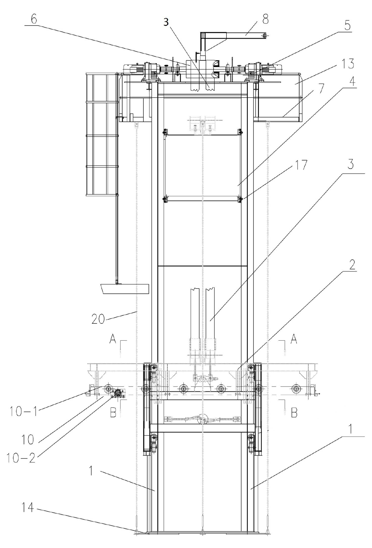
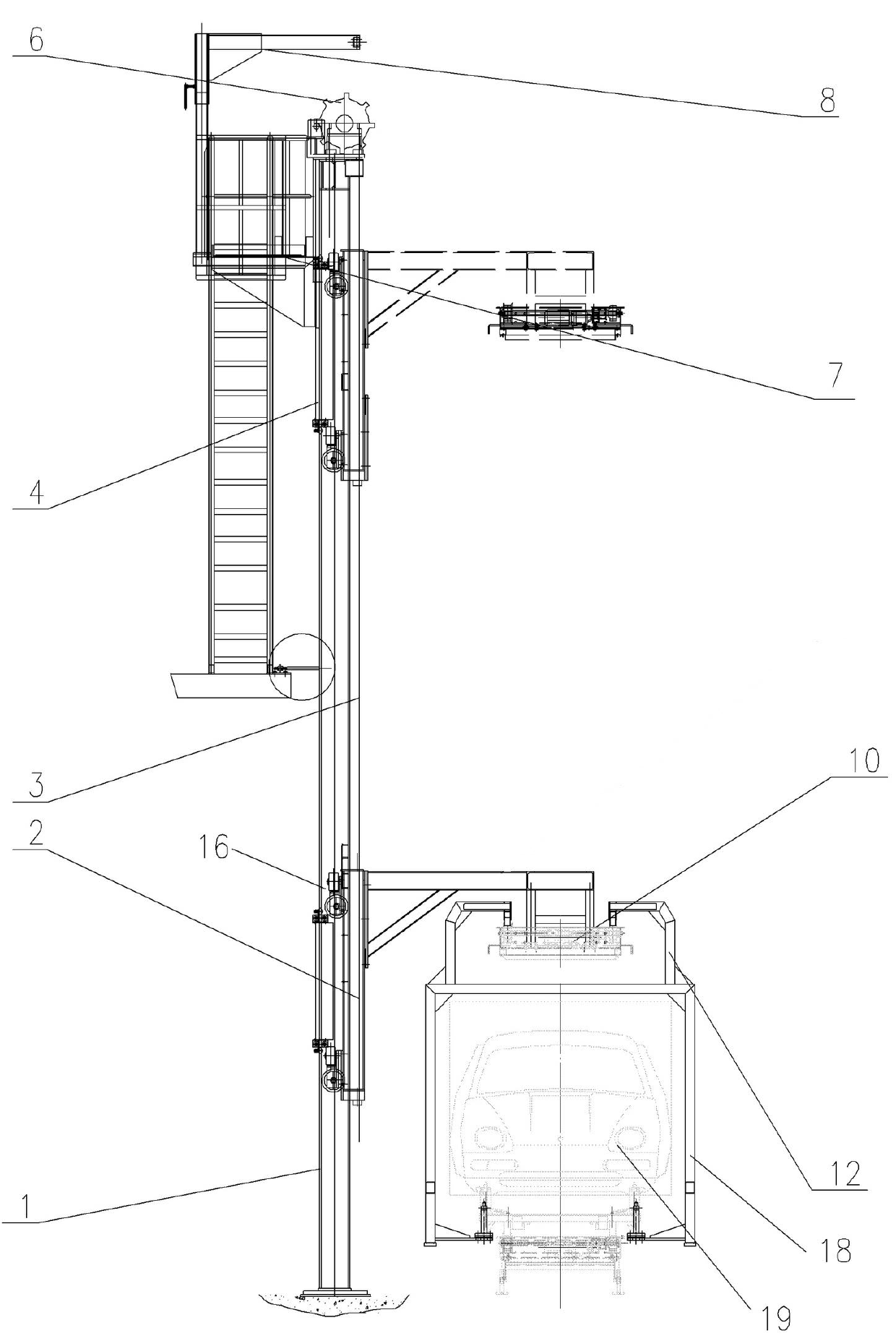
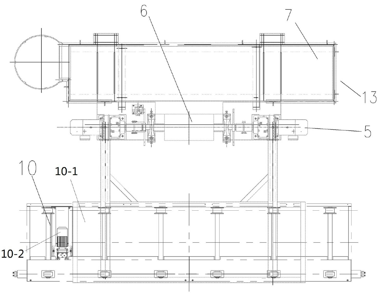
[0020] Embodiment 1 of a kind of skid lift Figure 1~5 As shown: it includes a base 14 and two H-shaped steel structure columns 1 arranged on the base 14 at intervals along the left and right directions and extending in the up and down direction. The H-shaped steel structure column 1 includes webs 1-1 and respectively fixed The front flange 1-2 and the rear flange 1-3 on the front and rear end faces of the web 1-1. The top of the two columns 1 is provided with a mounting frame 13, on which a drum reduction motor 5 is installed, and the output end of the drum reduction motor 5 is connected to a drum 6, and the drum 6 is wound with a front end wound to the two columns 1 The front side and the rear end are wound around to the middle of the rear sides of the two columns 1 and the belt 3 with the steel wire rope is passed through. The front and rear sides of the two upright columns 1 are equipped with a lifting frame 2 and a counterweight frame 4 respectively through the correspon...


PUM


Abstract

The invention relates to a slide lifter which comprises two H-shaped upright columns, a lifting frame and a counterweight frame, wherein each H-shaped upright column is provided with a web plate, a front flange and a rear flange; and the lifting frame and the counterweight frame are respectively assembled at the front sides and the rear sides of the upright columns through the guide of a lifting frame guide mechanism and a counterweight frame guide mechanism. The lifting frame guide mechanism comprises upper and lower lifting frame guide wheel sets; the upper and lower lifting frame guide wheel sets respectively comprise upper and lower lifting frame guide rollers matched with the corresponding web plates in a limiting manner and also respectively comprise upper and lower lifting frame supporting rollers matched with supports on the rear end surfaces of the corresponding front flanges or on the front end surfaces of the corresponding rear flanges in a limiting manner; the counterweight frame guide mechanism comprises upper and lower counterweight frame guide wheel sets; and the upper and lower counterweight frame guide wheel sets respectively comprise counterweight frame left and right guide rollers matched with the corresponding rear flanges in a guiding and limiting manner and counterweight frame front and rear guide roller sets. With the adoption of the slide lifter, the problem that the lifting frame guide mechanism and the counterweight frame guide mechanism are not easily assembled on the upright columns is solved.

Description

technical field [0001] The invention relates to skid conveying equipment, in particular to a skid lift. Background technique [0002] The existing skid lift includes two columns arranged side by side at intervals and both of which are of square tube structure. The front and rear sides of the columns are equipped with guides that can be lifted and lowered by the corresponding lifting frame guiding mechanism and the counterweight frame guiding mechanism respectively. lifting frame and counterweight frame. The transmission mechanism includes a chain with one end connected to the lifting frame and the other end connected to the counterweight frame after reversing through the corresponding reversing mechanism. The transmission mechanism also includes a sprocket driven by a power source and connected with the chain transmission. When working, the power source drives the chain to drive the lifting frame up and down, and the counterweight frame will move up and down accordingly to ...

Claims


Application Information

Patent Timeline
Patent Type & Authority Applications(China)
IPC IPC(8): B66F7/06B66F7/28
Inventor 高春生陈显赵亮王新峰张飞武
Owner ZHONGQI CHANGXING LUOYANG ELECTROMECHANICAL EQUIP ENG
Why Eureka
Try Eureka