Wind generating set and hydraulic motor thereof

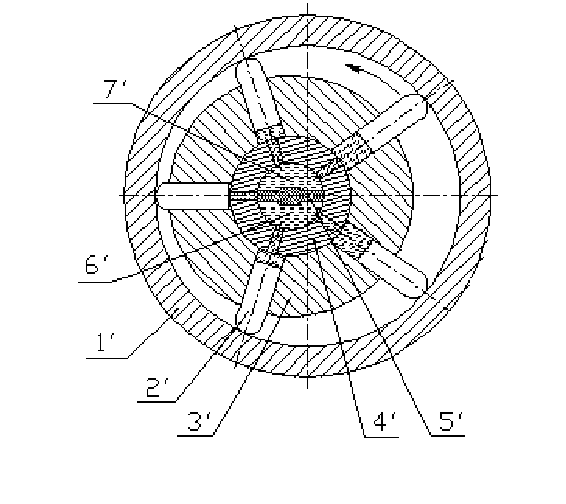
A hydraulic motor and high-voltage technology, which is applied in the field of wind turbines and hydraulic motors, can solve the problems of reduced service life, wear of the oil distribution shaft 4', unbalanced radial force, etc., and achieve the effect of reducing wear and improving service life

Inactive Publication Date: 2012-07-11
SANY ELECTRIC CO LTD
View PDF2 Cites 6 Cited by
  • Summary
  • Abstract
  • Description
  • Claims
  • Application Information

AI Technical Summary

Problems solved by technology

However, the high-pressure oil in the high-pressure oil inlet chamber 6' will produce a radial force on the oil distribution shaft 4', and with the rotation, the radial force is unbalanced, which will cause the oil distribution shaft 4' to wear, thereby reducing its service life

Method used


Image

  • Wind generating set and hydraulic motor thereof
  • Wind generating set and hydraulic motor thereof
  • Wind generating set and hydraulic motor thereof

Examples


Embodiment Construction

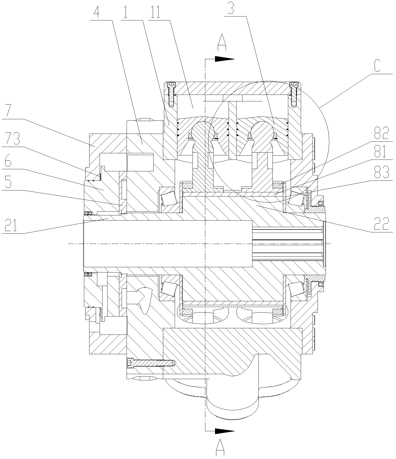
[0059] The core of the present invention is to provide a hydraulic motor, the structural design of which can prevent its oil distribution parts from being subjected to unbalanced radial force, thereby reducing its wear and improving its service life. In addition, another core of the present invention is to provide a wind power generating set including the hydraulic motor.

[0060] In order to enable those skilled in the art to better understand the technical solutions of the present invention, the present invention will be further described in detail below in conjunction with the accompanying drawings and specific embodiments.

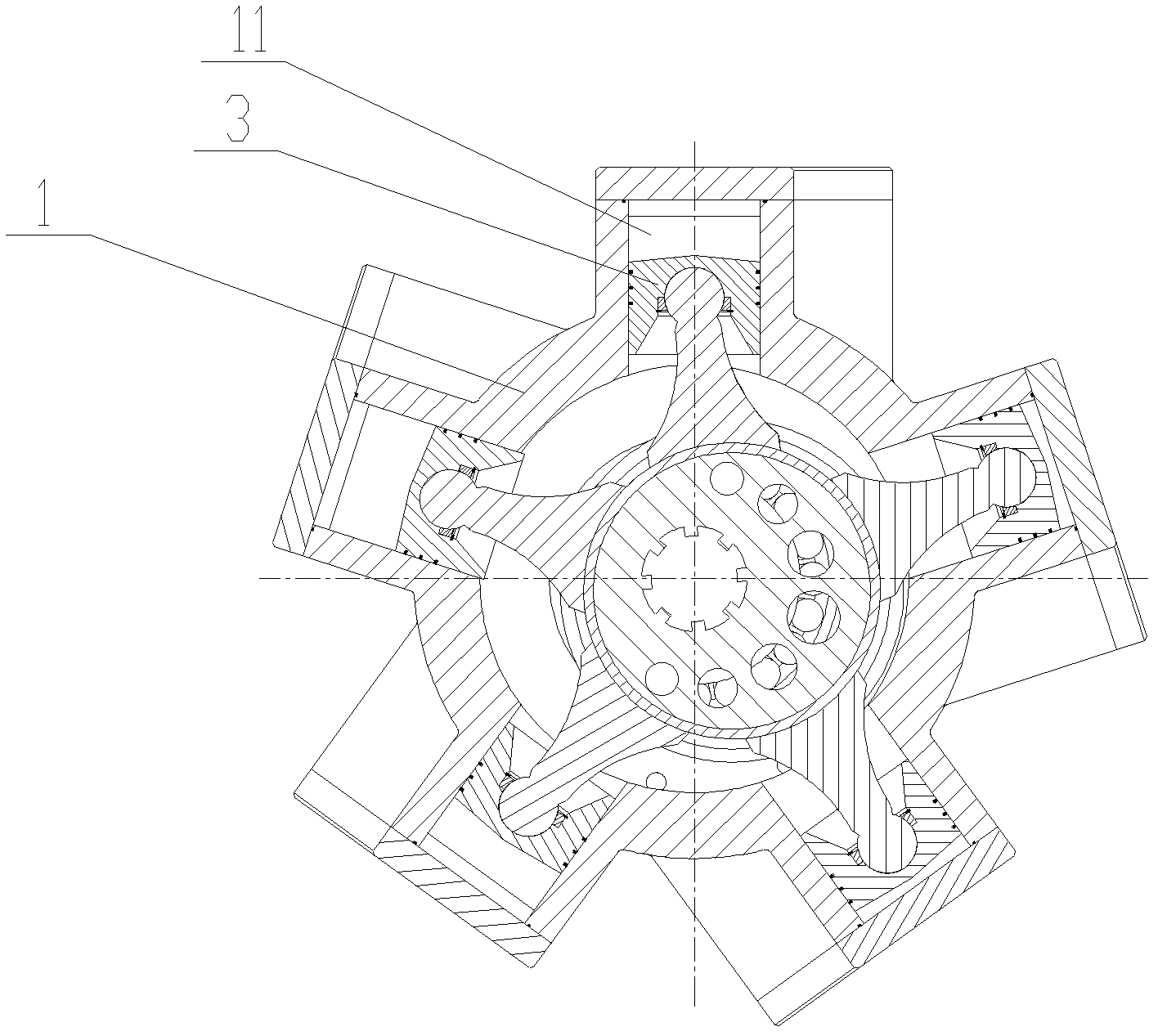
[0061] Please refer to Figure 2 to Figure 7 , figure 2 It is a structural schematic diagram of a hydraulic motor in an embodiment of the present invention; image 3 for figure 2 AA sectional view of the medium hydraulic motor; Figure 4 for figure 2 Schematic diagram of the cylinder body of the medium hydraulic motor; Pic 4-1 for Figure 4 ...


PUM


Abstract

The invention discloses a hydraulic motor. A symmetrical shaft (21) rotationally penetrates through a middle end cap (4), the middle end cap (4) is provided with a plurality of middle end cap oil passages (41) which are communicated with different plunger cavities (11) respectively. A valve plate (5) rotating along with the symmetrical shaft (21) is fixed to the outside of the symmetrical shaft (21) and is provided with a first oil cavity (51) and a second oil cavity (52), and the first oil cavity (51) and the second oil cavity (52) are communicated with the middle end cap oil passages (41) and alternated to form a high-pressure oil inlet cavity and a low-pressure oil return cavity. Any one of plunger components (3) moves to extend into the limit position, then the plunger cavity (11) with the plunger component begins to be communicated with the high-pressure oil inlet cavity, and when the plunger component (3) continues to move to extend out of the limit position, the plunger cavity (11) with the plunger component begins to be communicated with the low-pressure oil return cavity. The hydraulic motor with the structural design has the advantages that unbalanced radial force applied to the valve plate thereof can be avoided, abrasion of the hydraulic motor can be reduced, and the service life thereof can be prolonged. In addition, the invention discloses a wind generating set comprising the hydraulic motor.

Description

technical field [0001] The invention relates to the technical field of transmission components, in particular to a hydraulic motor. In addition, the invention also relates to a wind power generating set comprising the hydraulic motor. Background technique [0002] Although it has been more than 100 years since the first wind turbine was invented in Denmark, the composition and arrangement of the transmission chain of wind turbines have not changed fundamentally in recent decades, basically: impeller + main shaft + speed increaser Composition and arrangement of gearbox + coupling + generator. However, as the installed power of a single unit increases, the volume of the speed-up gearbox becomes larger and the structural design becomes more and more complicated. Especially in structural design, when the power is not very large (the installed capacity of a single machine generally does not exceed 2 MW), the most commonly used structural design of the speed-up gearbox is a firs...

Claims


Application Information

Patent Timeline
Patent Type & Authority Applications(China)
IPC IPC(8): F03D9/00F03C2/00
CPCY02E10/725Y02E10/72
Inventor 王初亮
Owner SANY ELECTRIC CO LTD
Why Eureka
Try Eureka