Inflator embedded with pressure gage

A technology for pressure gauges and pumps, applied in the field of pumps, can solve the problems of pressure gauge 40 loosening, unfavorable industrial design, and inability to effectively improve the efficiency of manufacturing and assembly, so as to achieve the effect of improving manufacturing and assembly efficiency and improving the quality of products

Active Publication Date: 2012-07-11
BETO ENG & MARKETING
View PDF9 Cites 8 Cited by
  • Summary
  • Abstract
  • Description
  • Claims
  • Application Information

AI Technical Summary

Problems solved by technology

[0008] 1. The overall appearance of the existing air pump is affected by the abrupt beam ring 41 of the pressure gauge 40, the pressure measuring nozzle 42 and the intermediary tube 13. As far as the overall appearance design is concerned, it is indeed unfavorable to industrial design
[0009] 2. The disassembly and assembly of the existing air pump pressure gauge 40 must be done by turning the lock bolt on the beam ring 41 with a hand tool. During the manufacturing and assembling process, hand tools (open-end wrench or socket) must be prepared, which cannot effectively improve the efficiency of manufacturing and assembling
[0010] 3. The clamp ring 41 on the pressure gauge 40 of the existing pump can only install the pressure gauge 40 on the cylinder 20 by locking the bolts. The lock bolt is easy to cause the pressure gauge 40 to loosen when the pump is used repeatedly for a long time.

Method used


Image

  • Inflator embedded with pressure gage
  • Inflator embedded with pressure gage
  • Inflator embedded with pressure gage

Examples


Embodiment Construction

[0075] In order to further explain the technical solution of the present invention, the present invention will be described in detail below through specific examples.

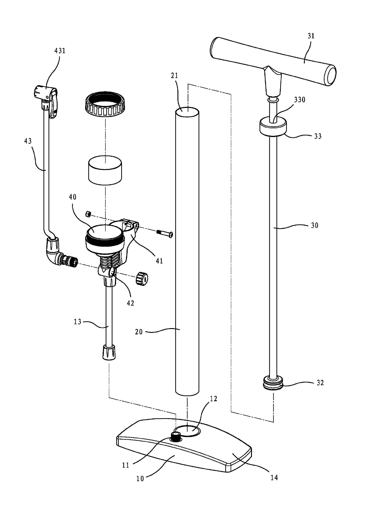
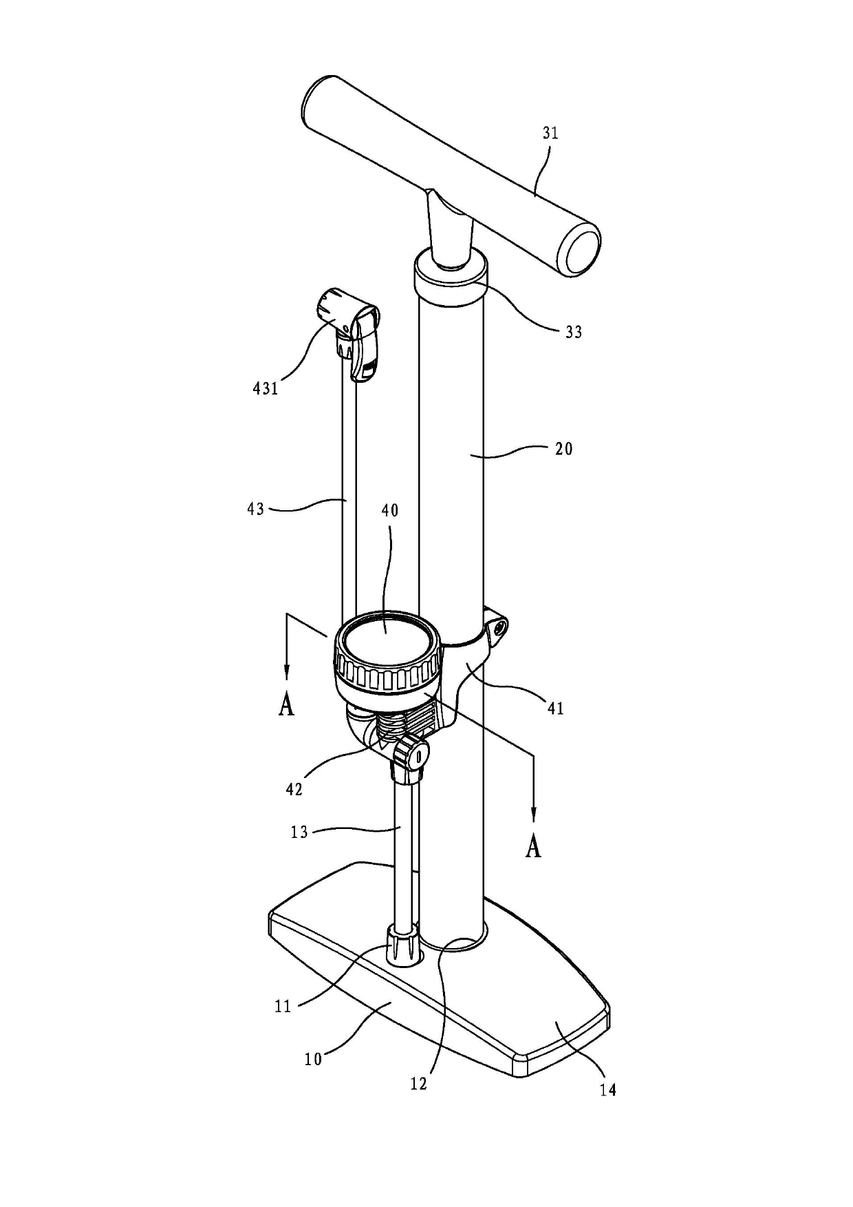
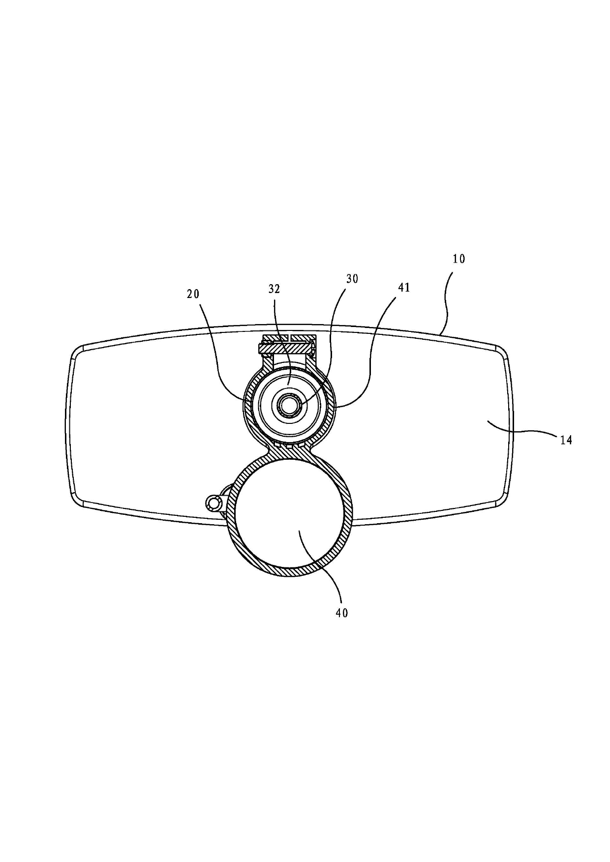
[0076] see Figure 4 to Figure 12 , the present invention includes:

[0077] A base 50, which is provided with a connection hole 511 and an assembly hole 512 with a larger diameter in the central part of the top surface, respectively. 511, the assembly hole 512, and a valve member 53 is installed in the cross passage 52. The valve member 53 has a concentric shaft portion 530 with a smaller diameter in the assembly hole 512. The top surface of the shaft portion 530 is provided with an air delivery hole 531 and a bottom. The end is radially outwardly expanded to form a shoulder 532, and the shoulder 532 is connected with a manifold 533 extending into the cross channel 52, and the manifold 533 is connected with a joint 534 protruding from the connecting hole 511. The joint 534 can provide One end of the air outl...


PUM


Abstract

The invention discloses an inflator embedded with a pressure gage, and the inflator comprises a base with an assembling hole, an inflating hose connected at the base, a cylinder butt-jointed with the assembling hole, a piston rod which can spurt the cylinder in a reciprocating manner to enable an air outlet hose to output pressurized gas, and a pressure gage installed in the cylinder, wherein an embedding groove is concavely arranged at the periphery of the cylinder along the axial direction; the assembling hole of the base is provided with a shutting nozzle communicated with the air outlet hose in the range of the embedding groove; the pressure gage is provided with an indentation part stretching over the embedding groove so as to be folded at the periphery of the cylinder; the indentation part is protrudingly provided with a hooking block which can extend into the embedding groove for positioning, so that the pressure gage can not be withdrawn from the embedding groove radially; the pressure gage is further provided with a pressure measuring nozzle opposite to the shutting nozzle; a decorative plate which can be inserted into the embedding groove is arranged between the pressure gage and the base; the pressure gage and the decorative plate can completely seal the embedding groove; and the back surface of the decorative plate is provided with a vent hole which can be communicated with the shutting nozzle and the pressure measuring nozzle.

Description

technical field [0001] The invention relates to a pressure gauge that can be disassembled and assembled without hand tools, and an air pump with a fixed pressure gauge. Background technique [0002] Please refer to Figure 1 to Figure 3 , existing pumps include: [0003] A base 10, the middle part of which is connected with an upwardly protruding joint 11 and an upwardly opening assembly hole 12, the joint 11 is upwardly connected with an intermediary pipe 13, and the bottom of the assembly hole 12 is equipped with a valve capable of one-way communication with the joint 11 (not shown in the figure), the two sides of the base 10 form stepping areas 14; [0004] A cylinder 20, the bottom of which can be inserted into the assembly hole 12 of the base 10. The cylinder 20 is provided with a cylinder hole 21 running through the upper and lower ends. The bottom of the cylinder hole 21 can be screwed to the one-way valve, so that the cylinder hole 21 The gas can be connected to th...

Claims


Application Information

Patent Timeline
Patent Type & Authority Applications(China)
IPC IPC(8): F04B33/00
Inventor 王罗平
Owner BETO ENG & MARKETING
Why Eureka
Try Eureka