Switch circuit breaker structure

A circuit breaker and switch technology, applied in the field of switch circuit breaker structures, can solve the problems of low assembly efficiency, low installation accuracy, overheating of plastic parts, etc., and achieve the effects of high assembly efficiency, high installation accuracy, and reduction of the number of parts

Active Publication Date: 2014-03-26
XIAMEN HONGFA ELECTRICAL SAFETY & CONTROLS CO LTD +1
View PDF8 Cites 4 Cited by
  • Summary
  • Abstract
  • Description
  • Claims
  • Application Information

AI Technical Summary

Problems solved by technology

[0007] The purpose of the present invention is to provide a switch circuit breaker structure to solve the existing problems in the prior art that there are many parts, low assembly efficiency, low installation accuracy and easy failure due to overheating of plastic parts

Method used


Image

  • Switch circuit breaker structure
  • Switch circuit breaker structure
  • Switch circuit breaker structure

Examples


Embodiment Construction

[0036] In order to further explain the technical solution of the present invention, the present invention will be described in detail below through specific examples.

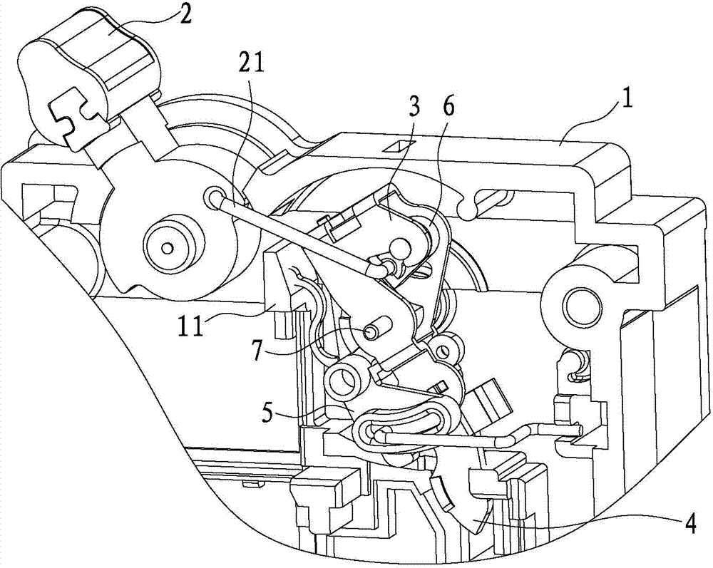
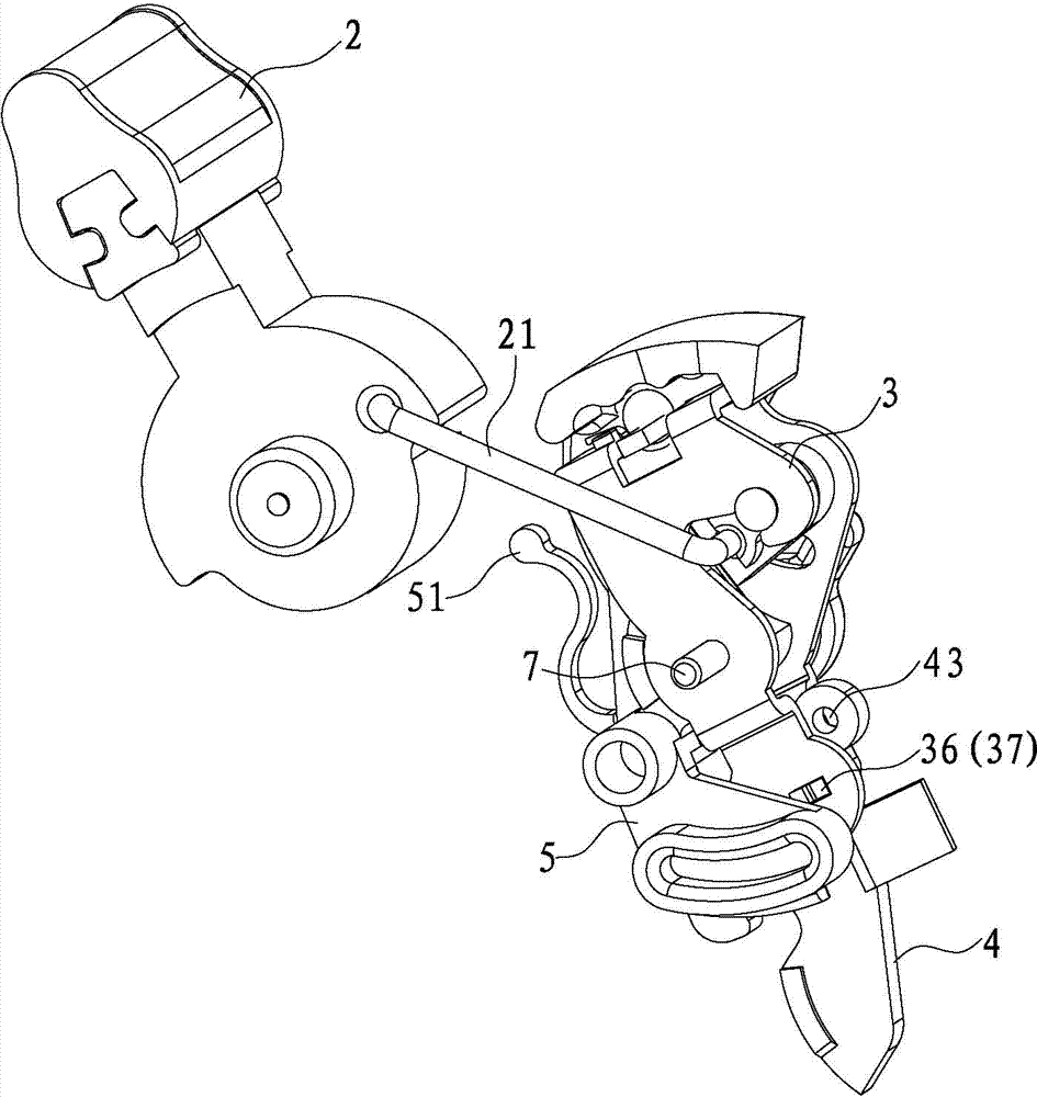
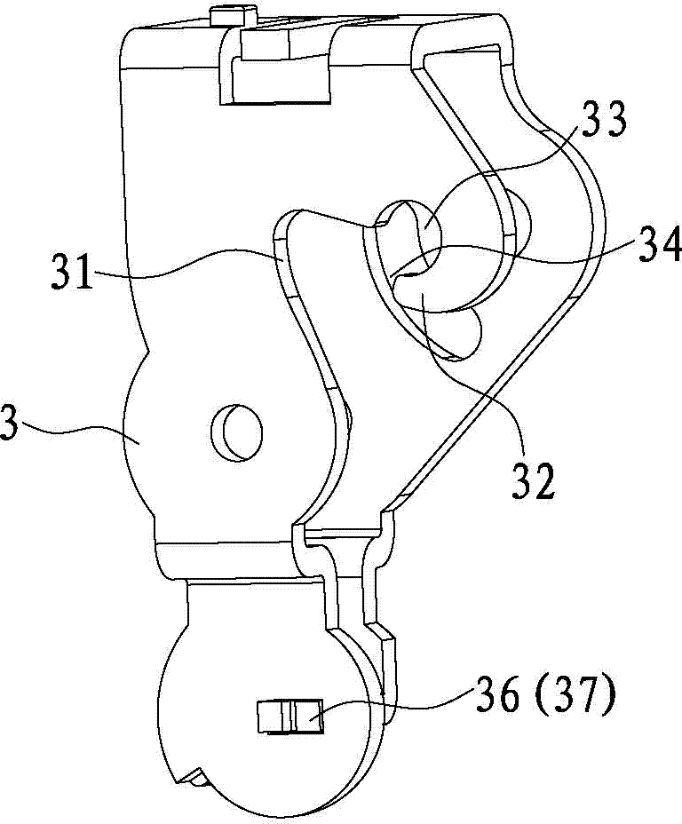
[0037] like Figure 1 to Figure 6 As shown, the structure of a switch circuit breaker involved in the present invention includes a housing 1, a hand operating mechanism 2, a connecting rod 21, a splint 3, a moving contact arm 4, a trip lever 5, a pawl 6, a support shaft 7 and a push rod (not shown in the figure), it should be noted that the core working principle of the present invention is basically the same as that of the patent documents in the background technology, and the same parts will not be described in detail here.

[0038] The improvement of the present invention is that the ratchet 6 is integrally formed with a first rotating shaft 61 and a second rotating shaft (not shown in the figure) which are respectively arranged on both sides of the ratchet 6, and the ratchet 6 passes through the first rotat...


PUM


Abstract

The invention discloses a switch circuit breaker structure. The switch circuit breaker structure comprises a shell, a hand control mechanism, a connecting rod, a clamping plate, a moving contact arm, a tripping rod, a pawl, a supporting shaft and a push rod, wherein a first rotary shaft and a second rotary shaft are formed on the pawl in an integral injection molding mode, and are arranged on the two sides of the pawl respectively, and the pawl is connected to the clamping plate through the first rotary shaft and the second rotary shaft in a rotatable mode. When the switch circuit breaker structure is assembled, assembly can be accomplished only by using the first rotary shaft and the second rotary shaft to assemble the pawl on the clamping plate, shafts or shaft sleeves are omitted, and installation accuracy of parts is improved; the number of the parts of the switch circuit breaker structure is reduced, and production efficiency, assembling efficiency and quality are improved.

Description

technical field [0001] The invention relates to the field of line protection switches, and more specifically relates to a switch circuit breaker structure. Background technique [0002] Chinese patent document CN1210747C discloses a protective switch device, which includes a hand-operated mechanism, a connecting rod, a splint, a moving contact arm, a trip lever, a pawl, a first support shaft, a support shaft and a push rod, and the support shaft is a The fixed rod, the splint and the trip lever are all in a rotatable state with the support shaft as the rotation axis. The splint, the moving contact arm and the pawl are also rotatably connected to the first support shaft, and the hand control mechanism is connected through the connecting rod. , The pawl is supported and rotatably connected to the pawl, the pawl can be buckled with the trip lever, and the lower end of the moving contact arm is also formed with a fixed contact to form a contact pair. The trip lever moves to sep...

Claims


Application Information

Patent Timeline
Patent Type & Authority Applications(China)
IPC IPC(8): H01H71/10
Inventor 王慧德徐明
Owner XIAMEN HONGFA ELECTRICAL SAFETY & CONTROLS CO LTD
Why Eureka
Try Eureka