Clamping and rotating device and sleeve mounting device

A technology of rotating device and mounting device, which is applied in metal processing, metal processing equipment, manufacturing tools, etc., can solve the problems of lower production efficiency and complicated torque wrench, and achieve the effect of improving production and assembly efficiency

Pending Publication Date: 2018-10-26
CHINA MINSHENG ZHUYOU
View PDF0 Cites 4 Cited by
  • Summary
  • Abstract
  • Description
  • Claims
  • Application Information

AI Technical Summary

Problems solved by technology

[0004] However, at present, the connection of the sleeve is mostly manually installed, which reduces the production efficiency. Because the installation of the sleeve needs to reach a certain pre-tightenin

Method used


Image

  • Clamping and rotating device and sleeve mounting device
  • Clamping and rotating device and sleeve mounting device
  • Clamping and rotating device and sleeve mounting device

Examples


Embodiment Construction

[0033] The present invention will be described in detail below with reference to the accompanying drawings. The description in this part is only exemplary and explanatory, and should not have any limitation on the protection scope of the present invention. In addition, according to the description of this document, those skilled in the art can correspondingly combine the features in the embodiments in this document and in different embodiments.

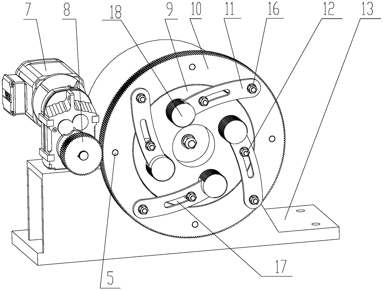
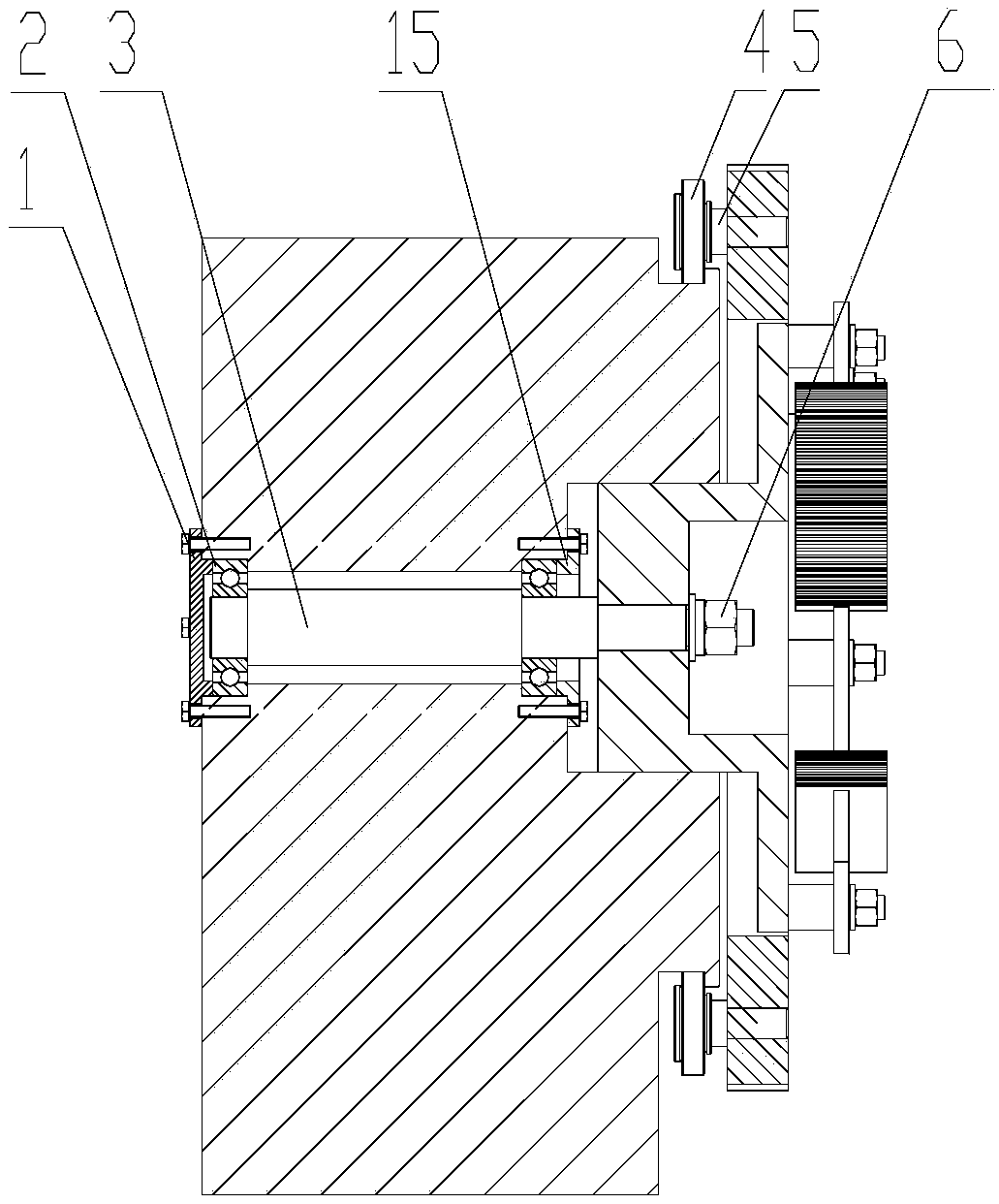
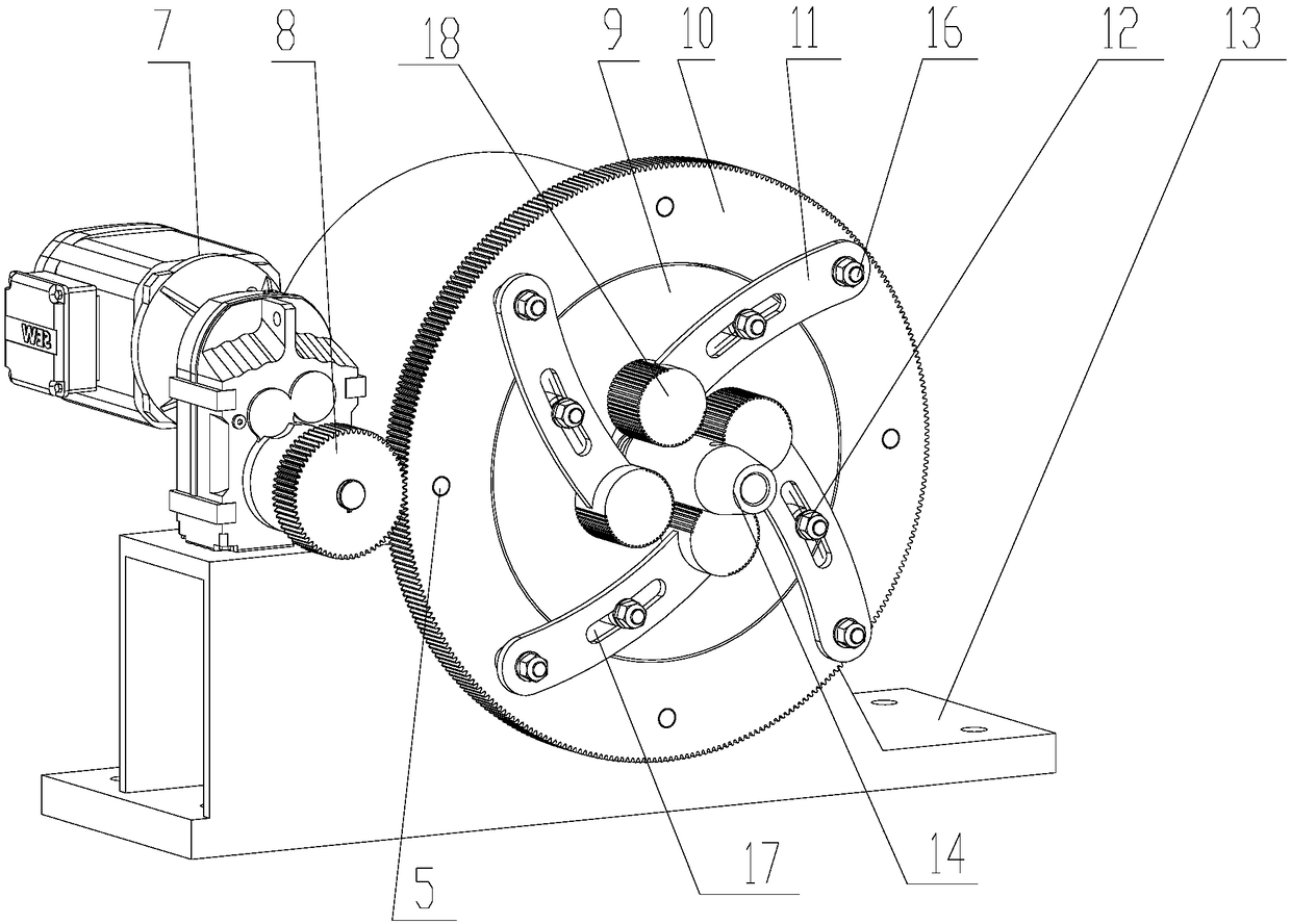
[0034] The embodiment of the present invention is as follows, such as figure 1 , A clamping and rotating device 25, comprising a driving turntable 10, a driven turntable 9 and a turntable driving member 7, the driving turntable 10 is a ring disk, the driven turntable 9 is arranged in the driving turntable 10, the The driving turntable 10 and the driven turntable 9 are coaxially arranged. The driving turntable 10 and the driven turntable 9 are respectively provided with a mounting shaft 16 and a limiting member 12, and the driving turntabl...


PUM


Abstract

The invention relates to a clamping and rotating device. The clamping and rotating device comprises a driving rotary disc, a driven rotary disc and a rotary disc driving part, wherein the driving rotary disc is an annular disc; the driven rotary disc is arranged in the driving rotary disc; the driving rotary disc is coaxial with the driven rotary disc; mounting shafts and limiting parts are respectively arranged on the driving rotary disc and the driven rotary disc; the driving rotary disc is connected with the driven rotary disc through a plurality of cranks; the cranks are symmetrically arranged along the center of the driven rotary disc; one end of each crank is articulated with each mounting shaft; a clamping part is arranged on each crank; the clamping parts of the plurality of cranksare used for forming a clamping space; a guide curved groove is formed in each crank; a limiting part is arranged in each guide curved groove; the rotary disc driving part is capable of driving the driving rotary disc to rotate and drive the clamping parts to move to the center or the periphery of the driven rotary disc. The clamping and rotating device is capable of providing certain pre-tightening force to sleeves in the process of mounting the sleeves, so that the mounting strength of the sleeves can be ensured; meanwhile, the sleeves can be directly driven to rotate, so that the sleeves and steel bars can be mounted and butted; the technical problem that the sleeves are clamped and mounted is solved; the producing and assembling efficiency is improved.

Description

Technical field [0001] The invention belongs to the technical field of steel bar processing, and specifically relates to a clamping rotating device and a sleeve mounting device. Background technique [0002] In the construction industry, in the construction of reinforced concrete structures, when the length of the component exceeds the length of the direct supply of steel, the steel must be extended. There are three connection methods for steel bar joints: binding, welding, and mechanical connection. Among them, the steel bar binding and lap method is time-consuming and labor-intensive, and the steel bar connection has low tensile performance. This connection method cannot be applied to the building facade with high requirements. Although the welding connection method can save steel, improve structural force performance, improve work efficiency, and reduce costs, it is affected by factors such as personnel, temperature, weather, and equipment, and there are some drawbacks in the...

Claims


Application Information

Patent Timeline
IPC IPC(8): B23P19/04
CPCB23P19/001B23P19/006B23P19/04
Inventor 林艳江
Owner CHINA MINSHENG ZHUYOU
Why Eureka
Try Eureka