Capacity-varying rotary type compressor

A technology of rotary compressor and compression mechanism, applied in the direction of rotary piston machinery, rotary piston pump, mechanical equipment, etc., can solve the problems of limited application scope, technical difficulty of sliding vane static, and difficulty in stopping the movement of the sliding vane. , to achieve the effect of easy promotion and application

Active Publication Date: 2012-07-11
GUANGDONG MEIZHI COMPRESSOR
View PDF4 Cites 9 Cited by
  • Summary
  • Abstract
  • Description
  • Claims
  • Application Information

AI Technical Summary

Problems solved by technology

[0004] However, the problem is that the vane static technology in variable capacity rotary compressors with vane springs is difficult and the application range is relatively limited
The reason for this is variable capacity rota

Method used


Image

  • Capacity-varying rotary type compressor
  • Capacity-varying rotary type compressor
  • Capacity-varying rotary type compressor

Examples


Embodiment 1

[0066] In this embodiment, two slide vanes consisting of a first slide vane and a second slide vane, and exhaust holes adjacent to each slide vane are arranged in one cylinder. When the first slide is in motion, the movement of the second slide is interrupted, which is called mode A. Conversely, when the movement of the first slide is interrupted, the second slide moves, which is called mode B. Due to the existence of these two modes, a variable capacity rotary compressor with two-stage displacement control can be performed.

[0067] Hereinafter, the specific content of this Embodiment 1 is demonstrated according to drawing.

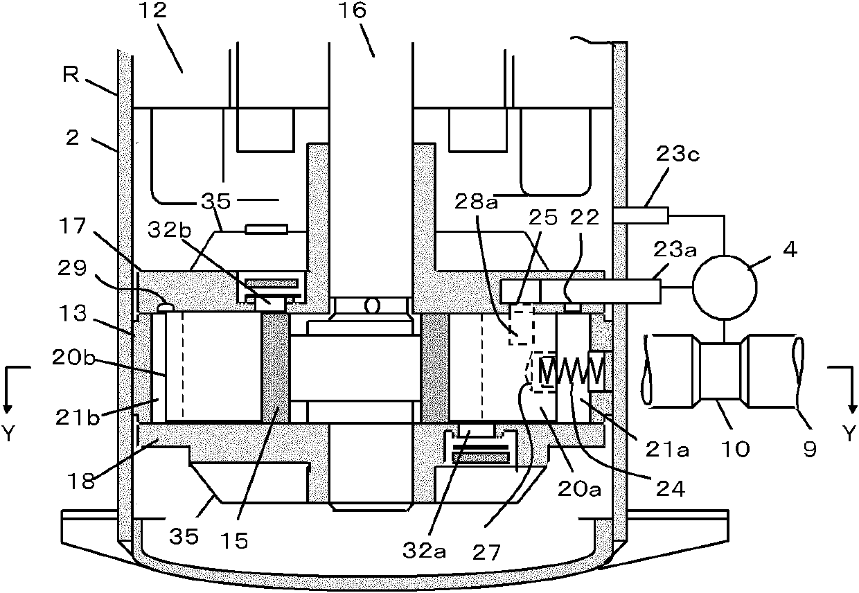
[0068] see figure 1 , is a longitudinal section view of a rotary compressor with two vanes in one cylinder, showing its internal structure.

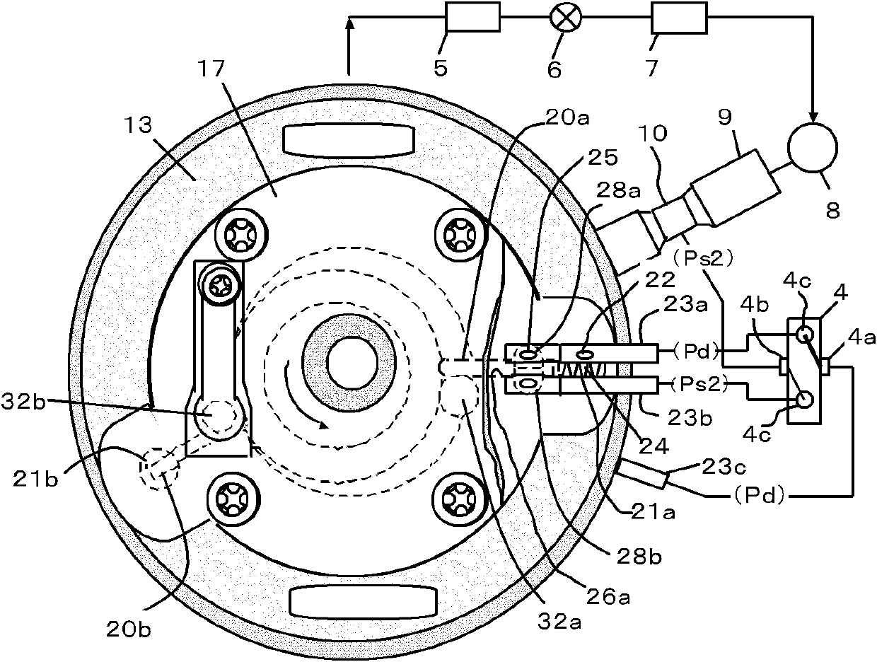
[0069] see figure 2 ,for figure 1 The cross-sectional view taken along the Y-Y line in FIG. 2 shows an example of a cross-section of the above-mentioned rotary compressor and a refrigeration cycle system equi...

Embodiment 2

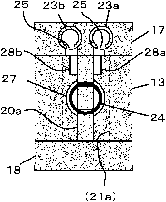
[0124] In Embodiment 1, different pressures are applied to the left and right sliding sides of the first sliding piece 20a sliding on the side wall of the first sliding piece groove 26a, so that the first sliding piece 20a is limited to the first sliding surface. slide slot 26a to stop it. In Embodiment 2, the purpose is to apply different pressures on the upper and lower sliding sides of the first sliding piece 20a to make the first sliding piece 20a stationary toward the main bearing 17 or the auxiliary bearing 18 .

[0125] see Figure 8 , the first connecting pipe 23a and the second connecting pipe 23b are mounted on the outer peripheries of the main bearing 17 and the sub-bearing 18, respectively. Communication holes 25 communicating with the first connecting pipe 23 a and the second connecting pipe 23 b are respectively provided at the tips thereof. The two communication holes 25 respectively open toward the upper and lower sliding sides of the first sliding piece 20a....

Embodiment 3

[0130] see Figure 9 , the present embodiment 3 is an embodiment in which the rotary compressor R disclosed in the embodiment 1 is mounted in a heating and cooling air conditioner having a four-way valve.

[0131] The first connecting pipe 23a of the rotary compressor R communicates with point S between the four-way valve and the heat exchanger 41 on the system, and the second connecting pipe 23b communicates with T between the four-way valve 4 and the heat exchanger 43 point.

[0132] As a result, during the heating operation, point S is on the high pressure side and point T is on the low pressure side, so the operation of the rotary compressor R is in mode A. During cooling operation, point S is the low-pressure side, and point T is the high-pressure side. Therefore, the rotary compressor R operates in mode B, and the capacity of the compressor decreases.

[0133] In Embodiment 3, the four-way valve required in the heating and cooling air conditioner is used, so the four-w...


PUM


Abstract

A capacity-varying rotary type compressor comprises a compression mechanism arranged in a casing. The compression mechanism comprises a cylinder. The cylinder is provided with a first sliding piece groove, a first sliding piece cavity, a second sliding piece groove and a second sliding piece cavity, wherein the first sliding piece groove and the first sliding piece cavity accommodate a first sliding piece, and the second sliding piece groove and the second sliding piece cavity accommodate a second sliding piece. A sliding piece spring is arranged in the first sliding piece cavity, an air suction hole in abutting connection with the first sliding piece is arranged on the cylinder, two opposite sliding side faces of the first sliding piece are provided with a first pressurizing cavity and a second pressurizing cavity, the first pressurizing cavity and the second pressurizing cavity are respectively communicated with a high-pressure pressure tapping hole and a low-pressure pressure tapping hole which are arranged on a four-way valve outside the casing, the second pressurizing cavity is communicated with the second sliding piece through a communicating passage, the pressure of the first pressurizing cavity and the pressure of the second pressurizing cavity are switched through the four-way valve so that stopping of the first sliding piece and stopping of the second sliding piece are alternately performed or removed. The capacity-varying rotary type compressor has the advantages that the energy utilizing rate is improved, the displacement of the compressor is changed, the refrigerating capacity is controlled easily, and the applied range is wide.

Description

technical field [0001] The invention relates to a variable displacement rotary compressor. Background technique [0002] In recent years, methods of improving air conditioning capacity control and energy efficiency by varying the motor speed using inverter technology have gained popularity. However, this method is technically more difficult to apply, and in addition to the problem that the increase in the number of electronic components affects reliability, there is also a disadvantage of high cost. [0003] In order to deal with this problem, technical research on capacity control through variable displacement rotary compressors is being carried out, so that the technical solution for improving air-conditioning capacity control is relatively easy to apply, and it is also more favorable in terms of reliability and cost. [0004] However, the problem is that the static technology of the vane in the variable capacity rotary compressor with the vane spring is relatively diffic...

Claims


Application Information

Patent Timeline
IPC IPC(8): F04C18/356
Inventor 小津政雄李华明
Owner GUANGDONG MEIZHI COMPRESSOR
Why Eureka
Try Eureka