Method for calibrating electrically scalable continuous valve

A proportional, bypass valve technology used in volumetric testing/calibration, non-electric variable control, control/regulation systems, etc., to solve problems such as consumption

Pending Publication Date: 2021-11-26
ROBERT BOSCH GMBH
View PDF1 Cites 2 Cited by
  • Summary
  • Abstract
  • Description
  • Claims
  • Application Information

AI Technical Summary

Problems solved by technology

Even if the calibrated orifice is integrated into a continuously adjustable bypass valve present in the hydraulic system via which pressure medium can flow from the pressure connection of the hydraulic pump to the tank, This still means increased cost

Method used


Image

  • Method for calibrating electrically scalable continuous valve
  • Method for calibrating electrically scalable continuous valve
  • Method for calibrating electrically scalable continuous valve

Examples


Embodiment Construction

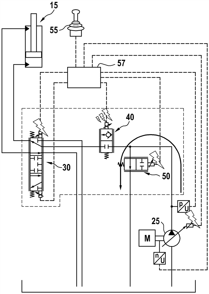
[0031] according to figure 1 The hydraulic system comprises a double-acting hydraulic cylinder 15 configured as a differential cylinder, for example for moving components of a digging arm, and having a cylinder housing 16, a piston 17 (a piston rod 18 in protruding from the piston on one side) the interior of the cylinder housing is divided into a piston rod-distal cylinder chamber 19 and a piston rod-side cylinder chamber 20.

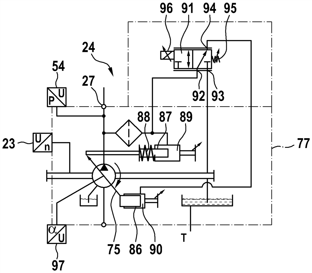
[0032] In addition, according to figure 1 The hydraulic system comprises a hydraulic pump 25 which can be adjusted on one side between a minimum value and a maximum value in terms of the displacement of the hydraulic pump by means of an adjusting device 24, the hydraulic pump being configured as a shaft in the form of a swash plate to a piston pump, and this hydraulic pump can be driven, for example, by a diesel engine. The hydraulic cylinders 15 and usually other hydraulic cylinders or hydraulic motors which are not shown can be supplied with pressu...


PUM


Abstract

The invention relates to a method for calibrating a continuous valve which is arranged in a hydraulic system and can be adjusted proportionally with respect to an actuation signal of an electronic control unit. According to the invention, the method comprises the following steps: 1) regulating the pump pressure to a preset pressure when the continuous valve is closed; 2) detecting a value at least for the displacement of the hydraulic pump; 3) changing, in particular raising, the control signal of the continuous valve starting from the initial control signal until a difference between a current pump volume flow rate and a predetermined pump volume flow rate corresponding to a predetermined volume flow rate is detected in the case of a closed flow cross-section of the continuous valve; 4) determining an offset of the control signal by comparing the control signal of the continuous valve detected when the predetermined volume flow is reached with a theoretical control signal.

Description

technical field [0001] The invention relates to a method for calibrating a continuous valve which can be adjusted proportionally with respect to an actuation signal of an electronic controller, said calibration taking into account the deviation of said actuation signal in the operating point: There is a predetermined pressure difference across the continuous valve and a predetermined volume flow through the continuous valve. Usually such continuous valves can be directly actuated electrically or electrohydraulically by means of proportional electromagnets. For example after being installed on a mobile work machine (such as an excavator), during operation, such a continuous valve can convey pressurized fluid from the pressure connection of the hydraulic pump to the hydraulic consumer. The hydraulic pump, in terms of its value The displacement that can be detected can be adjusted and the pump pressure of the hydraulic pump can be regulated. Background technique [0002] For ...

Claims


Application Information

Patent Timeline
Patent Type & Authority Applications(China)
IPC IPC(8): F15B13/02F15B15/14F15B19/00
CPCF15B13/02F15B15/14F15B19/00F15B19/002F15B2211/20546F15B2211/20553F15B2211/327F15B2211/30515F15B2211/3144F15B2211/455F15B2211/426F15B2211/413F15B2211/50536F15B2211/41509F15B2211/526F15B2211/513F15B2211/6309F15B2211/633F15B2211/6652F15B2211/6346F15B2211/6333F15B2211/7053F15B2211/6313G01F25/0092E02F9/2235E02F9/2228F15B21/08F15B11/006F15B11/0423E02F9/2221F04B49/06F04B49/22F04B49/16G05D16/2026F15B2211/205F15B2211/25G01F25/10
Inventor W·福特B·塞莱斯S·奥施曼
Owner ROBERT BOSCH GMBH
Why Eureka
Try Eureka