Fixing lock for ball retainer for slide rail
A cage and fixed lock technology, applied in the field of slideways and slide rails, can solve the problems of increased man-hours, complicated installation and disassembly processes, increased production costs, etc., and achieves the effects of easy manufacture, simple structure, and simple overall structure
- Summary
- Abstract
- Description
- Claims
- Application Information
AI Technical Summary
Problems solved by technology
Method used
Image


Examples
Embodiment 1
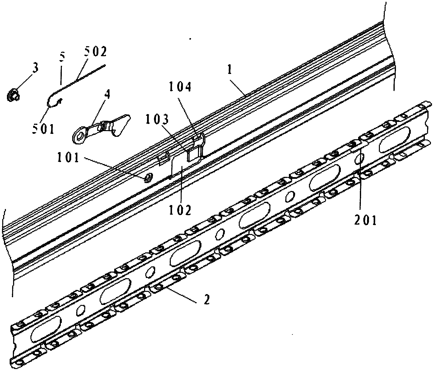
[0023] see figure 1 As shown, a ball cage fixed lock for a slide rail includes a slide rail outer frame 1 and a ball cage 2 slidably arranged in the slide rail outer frame 1 , on the slide rail outer frame 1 A fixed hole 101 and a movable cavity 102 are provided, the fixed hole 101 is located on one side of the movable cavity 102, and one end of a self-locking mechanism 4 is rotatably fixed to the outer frame 1 of the slide rail by a rivet 3 On the fixed hole 101, the other end is located in the movable cavity 102; the side of the ball cage 2 is provided with a drop groove 201, and the self-locking mechanism 4 is located at one end of the movable cavity 102. fall into the drop groove 201, thereby locking the ball cage 2 to prevent it from sliding further.
[0024] Further, one side of the movable cavity 102 is a limit stop 103 for preventing the self-locking mechanism 4 from laterally shifting, and the limit stop 103 is fixed on the outer frame 1 of the slide rail.
[0025] ...
Embodiment 2
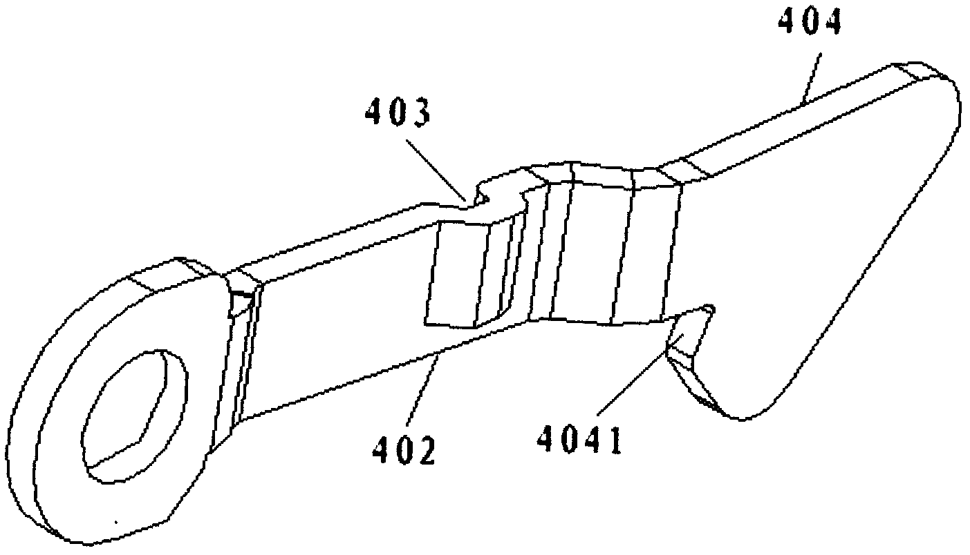
[0028] see figure 2 As shown, a ball cage fixed lock for a slide rail includes a slide rail outer frame 1 and a ball cage 2 slidably arranged in the slide rail outer frame 1 , on the slide rail outer frame 1 A fixed hole 101 and a movable cavity 102 are provided, the fixed hole 101 is located on one side of the movable cavity 102, and one end of a self-locking mechanism 4 is rotatably fixed to the outer frame 1 of the slide rail by a rivet 3 On the fixed hole 101, the other end is located in the movable cavity 102; the side of the ball cage 2 is provided with a drop groove 201, and the self-locking mechanism 4 is located at one end of the movable cavity 102. fall into the drop groove 201, thereby locking the ball cage 2 to prevent it from sliding further.
[0029] Further, one side of the movable cavity 102 is a limit stop 103 for preventing the self-locking mechanism 4 from laterally shifting, and the limit stop 103 is fixed on the outer frame 1 of the slide rail.
[0030]...
PUM
 Abstract
Description
Claims
Application Information
 - R&D
- Intellectual Property
- Life Sciences
- Materials
- Tech Scout
- Unparalleled Data Quality
- Higher Quality Content
- 60% Fewer Hallucinations
Browse by: Latest US Patents, China's latest patents, Technical Efficacy Thesaurus, Application Domain, Technology Topic, Popular Technical Reports.
© 2025 PatSnap. All rights reserved.Legal|Privacy policy|Modern Slavery Act Transparency Statement|Sitemap|About US| Contact US: help@patsnap.com