
Thermostatic bath for verifying temperature sensor paired with calorimeter

A technology of temperature sensor and constant temperature bath, which is applied in the field of constant temperature bath, can solve problems such as uneven heating and uneven temperature distribution, and achieve the effects of preventing energy waste, improving measurement accuracy, and improving energy utilization efficiency

Inactive Publication Date: 2012-07-11
NAT INST OF METROLOGY CHINA
View PDF8 Cites 3 Cited by
  • Summary
  • Abstract
  • Description
  • Claims
  • Application Information

AI Technical Summary

Problems solved by technology

In the traditional constant temperature tank, the heating part is used to heat the liquid, the temperature of the liquid near the heating part rises, and convection occurs with the surrounding liquid, so that the liquid in the tank gradually tends to a constant temperature. However, in actual use, it is found that Due to uneven heating, there is convection in the liquid in the vertical direction in the tank, and the temperature distribution in the tank is uneven

Method used


Image

  • Thermostatic bath for verifying temperature sensor paired with calorimeter
  • Thermostatic bath for verifying temperature sensor paired with calorimeter
  • Thermostatic bath for verifying temperature sensor paired with calorimeter

Examples


Embodiment Construction

[0016] The present invention will be further described below in conjunction with the accompanying drawings. Those skilled in the art should understand that the following examples are only for the convenience of understanding and implementing the present invention, and should not limit the scope of the present invention to specific structures.

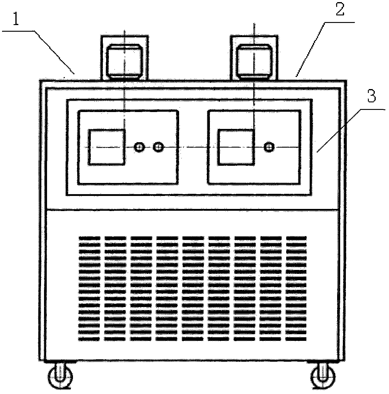
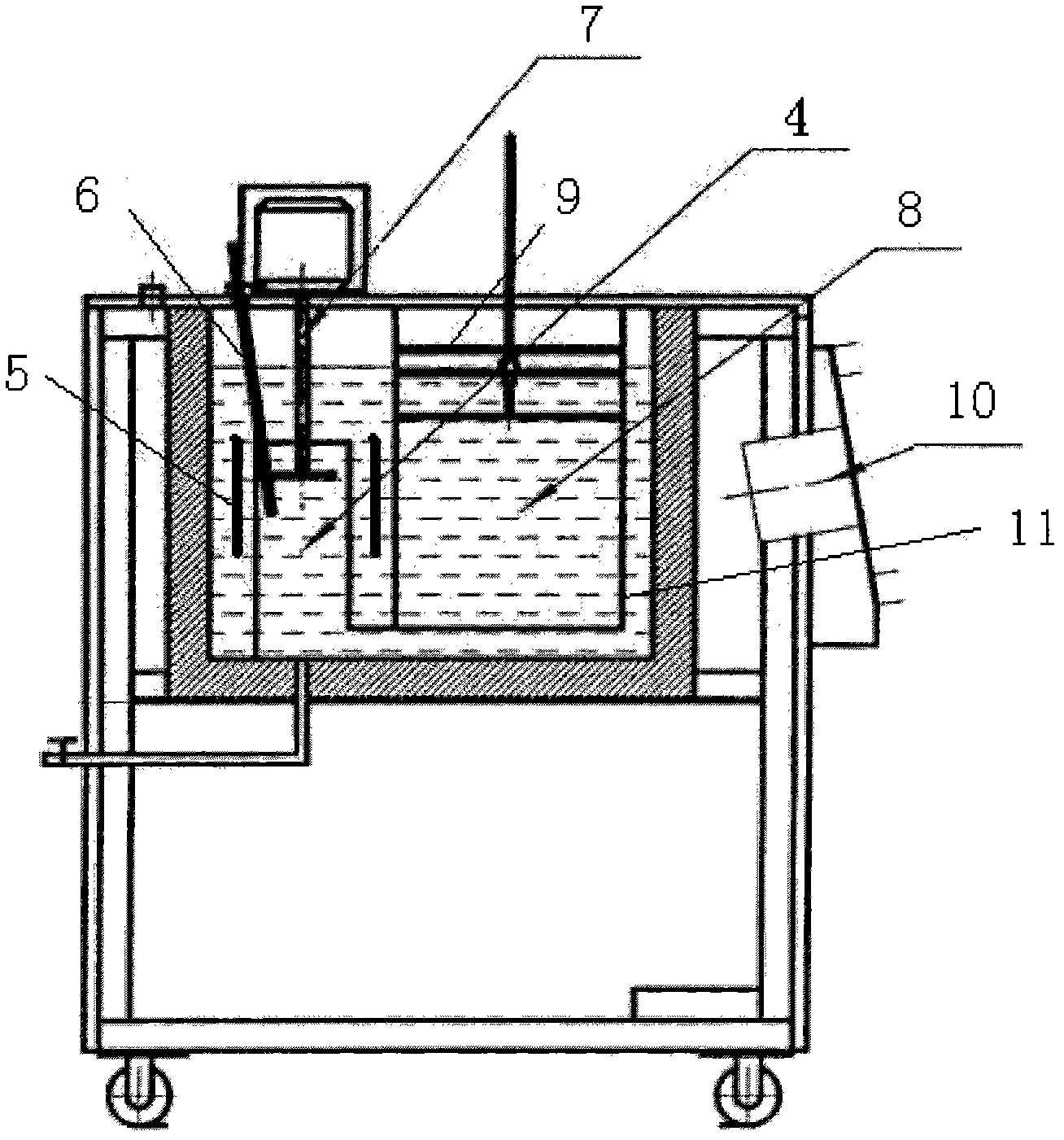
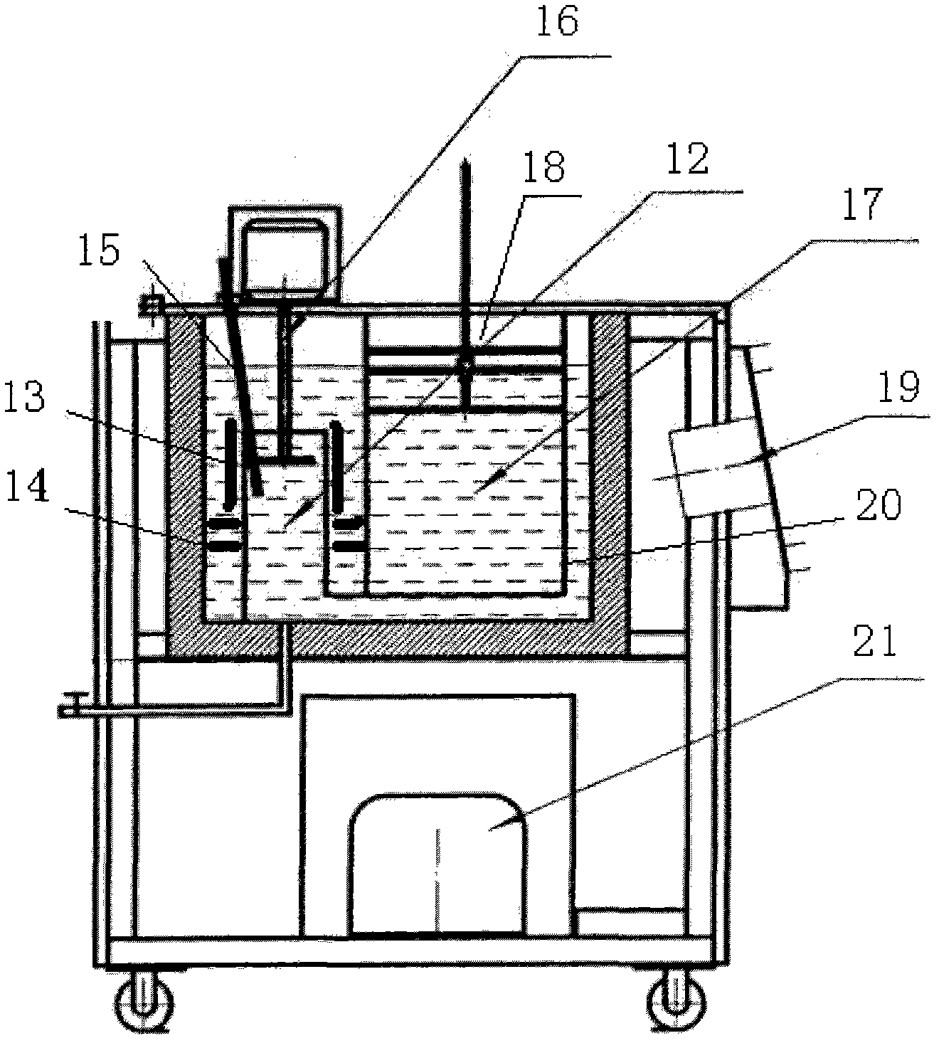
[0017] Such as figure 1 The shown temperature sensor verification constant temperature tank device includes a first tank body 1 and a second tank body 2 with different temperatures, and a control panel 3 for controlling and operating various functions of the constant temperature tank. The temperature range of the first tank 1 is: room temperature to 90°C; the temperature range of the second tank 2 is: 5°C to 90°C; the temperature of the first tank 1 and the second tank 2 can be controlled through the control panel 3, It specifically includes a large-scale temperature adjustment part and a small-scale fine-tuning part. The first tank bo...


PUM


Abstract

The invention relates to a thermostatic bath for verifying a temperature sensor paired with a calorimeter. The thermostatic bath comprises a first bath body, a second bath body and a control system controlling the first bath body and the second bath body respectively. The thermostatic bath is characterized in that the liquid in the mixing cavity of the first bath body flows into a first working cavity through a bottom passage, and the temperature of the liquid in the first working cavity is stable; and the liquid in the mixing cavity of the second bath body flows into a second working cavity through a bottom passage, and the liquid in the second working cavity is stable. The thermostatic bath provided by the invention can accurately verify the temperature sensor paired with the calorimeter, so as to improve the measuring accuracy of the calorimeter, facilitate the improvement on energy utilization efficiency and prevent energy waste.

Description

technical field [0001] The invention relates to a constant temperature tank, in particular to a constant temperature tank for verifying a paired temperature sensor of a heat meter. Background technique [0002] At present, heating is required in winter in northern my country. In order to save energy and reduce smoke and dust, most areas have centralized heating through heating networks, and the state stipulates that all new buildings starting from October 1, 2000 must involve, install and use heat metering facilities. In order to scientifically and rationally control and use heating energy and prevent energy waste, it is necessary to calibrate the accuracy of the heat meters used in large quantities to ensure the accuracy of the heat measured by the heat meters. The heat meter is mainly composed of a flow sensor, a paired temperature sensor and a calculator. The working principle of the heat meter is: install the paired temperature sensor on the inlet and outlet pipes of the...

Claims


Application Information

Patent Timeline
Patent Type & Authority Applications(China)
IPC IPC(8): G01K19/00
Inventor 王池李福学邱萍
Owner NAT INST OF METROLOGY CHINA
Learn More