Spiral screwing type sampler and sampling device
A sampling device and helical technology, which are applied in the field of samplers and sampling devices with the sampler, can solve the problems such as difficulty in reaching the weight volume by weight volume, sample particle size no longer being authentic, and inability to achieve sampling depth, etc. The effect of increased adaptation range, fast sampling speed and simple structure
- Summary
- Abstract
- Description
- Claims
- Application Information
AI Technical Summary
Problems solved by technology
Method used
Image
Examples
Embodiment 1
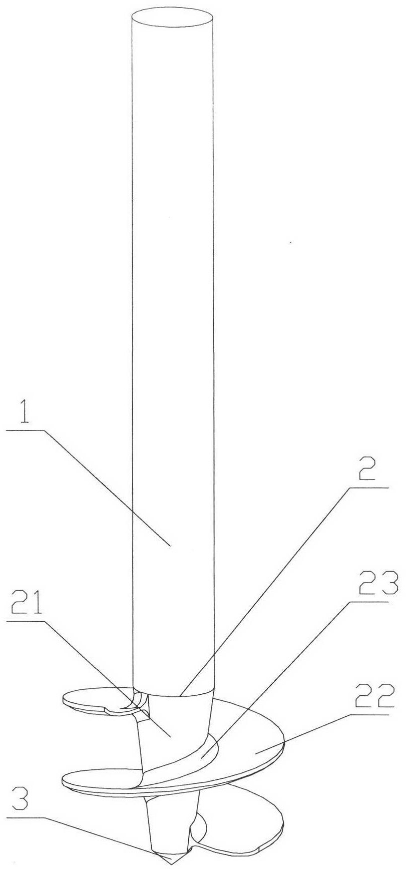
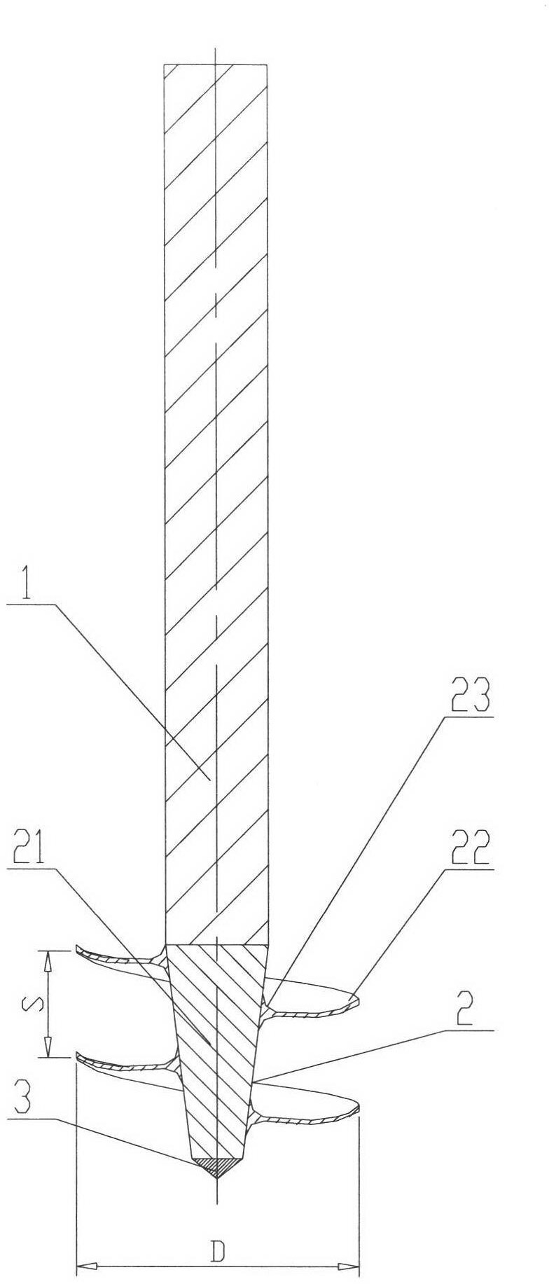
[0032] a kind of like Figure 1 ~ Figure 2 The shown screw-in sampler of the present invention comprises an upper sampling rod 1 and a lower screw lifter 2, and the screw lifter 2 includes a screw mandrel 21 and a helical blade wound around the helical mandrel 21 22. The upper surface of the screw blade 22 used to carry the mined material extends along the radial direction of the screw lifter 2 as a concave arc surface (more specifically, on the axial section passing through the central axis of the screw lifter 2 See, the upper surface of the helical blade 22 is a concave circular arc from the outside to the inside). In this embodiment, the side of the spiral mandrel 21 is an inverted conical surface, so that the sampler can be screwed into the collected material like a wood screw, which can not only reduce the driving force of the sampler, but also reduce the driving force of the driving device. The operating power is improved, and the sampler can better penetrate into the b...
Embodiment 2
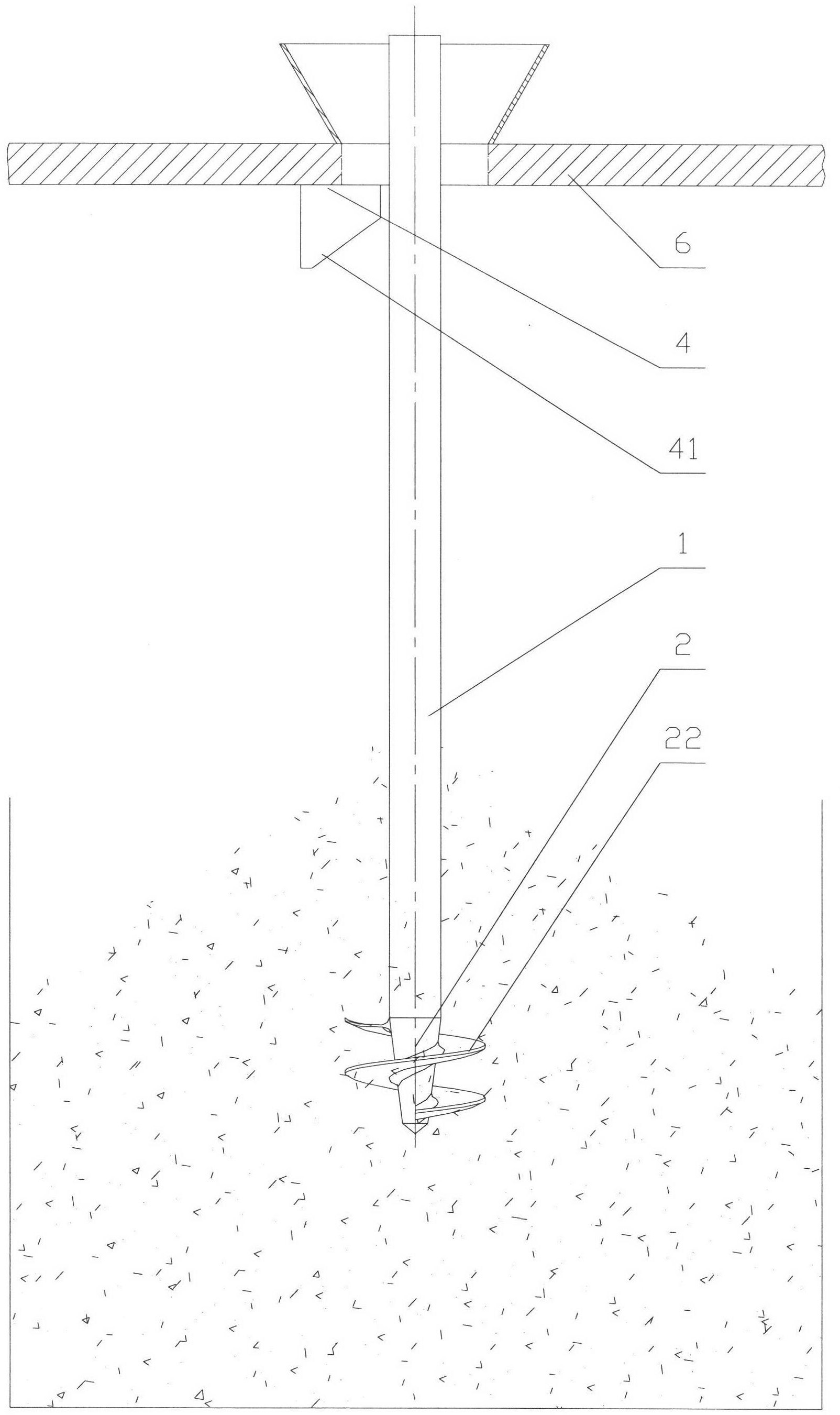
[0037] a kind of like Figure 3 ~ Figure 5 The shown sampling device without outer cylinder of the present invention mainly includes a frame 6, the middle part of the frame 6 passes through the screw-in type sampler of the above-mentioned embodiment 1, and the screw-in type sampler is not sleeved. Outer cylinder, the bottom of frame 6 is installed with a frame quantification device 4 near the position of screw-in type sampler, and frame quantification device 4 is mainly made up of the quantitative scraper 41 that is fixed on frame 6 bottoms.
[0038] The working principle of the sampling device without outer cylinder is as follows: firstly, the spiral screw-in sampler is lifted to the highest point (the highest point is located at the bottom of the frame 6), so that the top of the space profile where the helical blade 22 is distributed and the bottom of the frame 6 are installed. Quantitative scraper 41 contacts; Figure 4 As shown, when the helical screw-in sampler is vertic...
Embodiment 3
[0040] a kind of like Figure 6 ~ Figure 9 The shown sampling device with an outer cylinder of the present invention includes a frame 6, the middle part of the frame 6 passes through a hollow outer cylinder quantitative device 5, and the inner cavity of the outer cylinder quantitative device 5 is provided with the above-mentioned embodiment. 1, the screw-in sampler is provided with a sampling rod step 9 near the bottom of the sampling rod 1 of the spiral lifter 2 in the screw-in sampler, and the outer cylinder quantitative device 5 includes a device that can slide up and down along the sampling rod 1 (vertically The hollow cylinder 8 and the outer cylinder 51 fixedly connected to the bottom of the hollow cylinder 8, the hollow cylinder 8 and the sampling rod 1 are in clearance fit, the outer surface of the hollow cylinder 8 is provided with a sliding key 7, and the sliding key 7 is connected to the through hole of the frame 6 bottom plate With the cooperation of the feather ke...
PUM
| Property | Measurement | Unit |
|---|---|---|
| distance | aaaaa | aaaaa |
| diameter | aaaaa | aaaaa |
| diameter | aaaaa | aaaaa |
Abstract
Description
Claims
Application Information
 - R&D
- Intellectual Property
- Life Sciences
- Materials
- Tech Scout
- Unparalleled Data Quality
- Higher Quality Content
- 60% Fewer Hallucinations
Browse by: Latest US Patents, China's latest patents, Technical Efficacy Thesaurus, Application Domain, Technology Topic, Popular Technical Reports.
© 2025 PatSnap. All rights reserved.Legal|Privacy policy|Modern Slavery Act Transparency Statement|Sitemap|About US| Contact US: help@patsnap.com


