Shearing tester

A technology of shearing test and driving machine, applied in the field of shearing instrument, which can solve the problems of deformation of shearing box and lack of shearing tester, etc.

Inactive Publication Date: 2012-07-11
ZHEJIANG TUGONG INSTR
View PDF5 Cites 13 Cited by
  • Summary
  • Abstract
  • Description
  • Claims
  • Application Information

AI Technical Summary

Problems solved by technology

When the shearing instrument is working, the substance to be detected is put into the shearing box, and the shaft in the worm gear box is driven by the motor to drive the chain transmission mechanism to rotate, and the top axis of the worm gear box is protruded in the direction of the shearing box through the gear, continuously Push the shear box, and then the shear box pushes the force measuring ring, causing the shear box to deform until the substance to be tested is broken, and then measure the shear parameters of the substance to be tested according to the readings of the force measuring ring, the above is only suitable for volume comparison Small test pieces for shear tests
But along with the requirement of road construction constantly improves, the requirement to the shear test of test block also improves to some extent, at present, in the retrieval of the applicant, there is not yet a shear tester suitable for larger test block test

Method used


Image

  • Shearing tester
  • Shearing tester
  • Shearing tester

Examples


Embodiment Construction

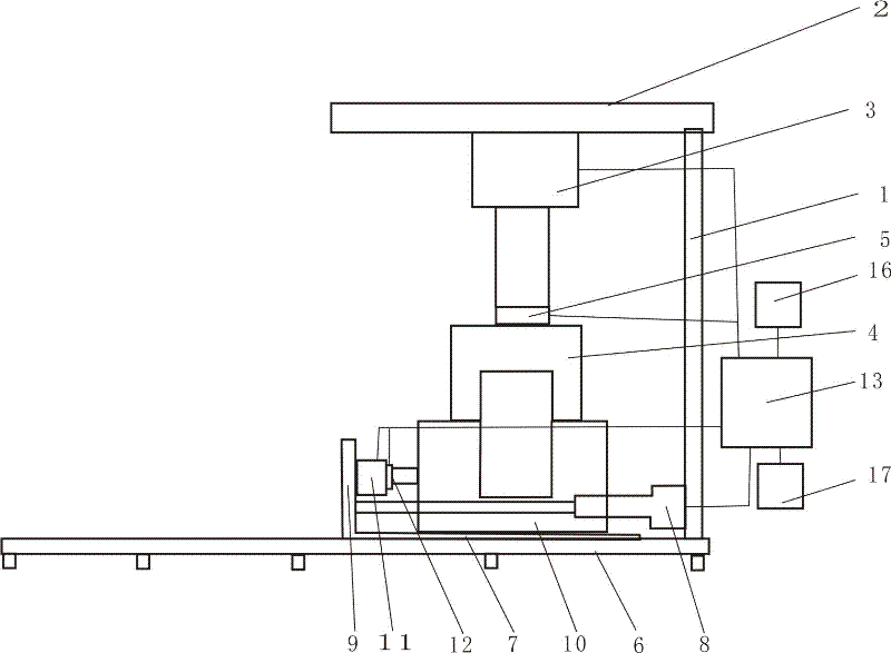
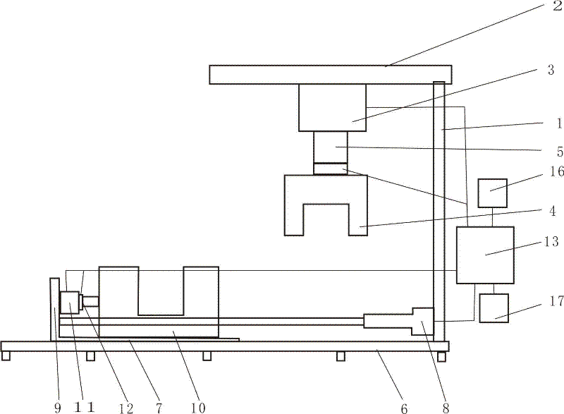
[0017] Such as figure 1 Shown, shear tester of the present invention, it comprises upper die assembly, lower die assembly and controller;

[0018] The upper mold assembly includes a bracket 1, a top block 2 fixed on the bracket, a vertical driving machine 3 is fixed below the top block 2, and the vertical driving machine 3 generally adopts an oil cylinder or an air cylinder. The lower end of machine 3 fixes upper half mold frame 4. A vertical pressure sensor 5 may be placed between the vertical driving machine 3 and the upper half frame 4 , and the vertical pressure sensor 5 is connected to a control module 13 for signals.

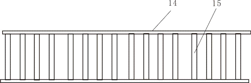
[0019] Described lower mold assembly comprises rail 6, the horizontal moving frame 7 on described rail 6, and described rail 6 comprises two parallel main rails 14, is arranged between described two parallel main rails. There are several rollers 15 (see image 3 ).

[0020] The horizontal moving frame 7 is connected with the support 1 through a horizon...


PUM


Abstract

The invention discloses a shearing tester, which comprises an upper die component, a lower die component and a controller. The upper die component comprises a bracket and a top block fixed on the bracket; a vertical driver is fixed below the top block; an upper half die frame is fixed at the lower end of the vertical driver; the lower die component comprises a track and a horizontal moving frame on the track; a lower half die frame is arranged on the horizontal moving frame; a shearing pressing piece is arranged between the lower half die frame and a vertical block of the horizontal moving frame; and a shearing force sensor is arranged at the outlet end of the shearing pressing piece. As a testing block is installed in a position outside a shearing testing area, the shearing tester is suitable for large-volume testing block tests, has a reasonable structure, at the same time adopts a control module for controlling, and is very convenient to operate.

Description

technical field [0001] The invention relates to a test instrument, in particular to a shearing instrument for testing soil sample blocks. Background technique [0002] As a kind of geotechnical testing instrument, the shear instrument is widely used in the soil quality analysis of buildings. The existing shear instrument is generally an electric direct shear, which includes a workbench, a motor on the workbench, a shear box, a force measuring ring and a top block etc. When the shearing instrument is working, the substance to be detected is put into the shearing box, and the shaft in the worm gear box is driven by the motor to drive the chain transmission mechanism to rotate, and the top axis of the worm gear box is protruded in the direction of the shearing box through the gear, continuously Push the shear box, and then the shear box pushes the force measuring ring, causing the shear box to deform until the substance to be tested is broken, and then measure the shear parame...

Claims


Application Information

Patent Timeline
Patent Type & Authority Applications(China)
IPC IPC(8): G01N3/24
Inventor 陈志明王士明
Owner ZHEJIANG TUGONG INSTR
Why Eureka
Try Eureka