Device for accurately bending printed circuit board

A printed circuit board and bending technology, which is applied in the field of devices for precise bending of printed circuit boards, can solve problems such as the inability to accurately control the degree of substrate bending and the inability to accurately find the substrate.

Inactive Publication Date: 2012-07-11
CHINA ACADEMY OF SPACE TECHNOLOGY
View PDF5 Cites 0 Cited by
  • Summary
  • Abstract
  • Description
  • Claims
  • Application Information

AI Technical Summary

Problems solved by technology

[0004] In previous operations, it was often impossible to accurately find the zero point at which the substrate began to bend, and the value

Method used


Image

  • Device for accurately bending printed circuit board
  • Device for accurately bending printed circuit board

Examples


Embodiment Construction

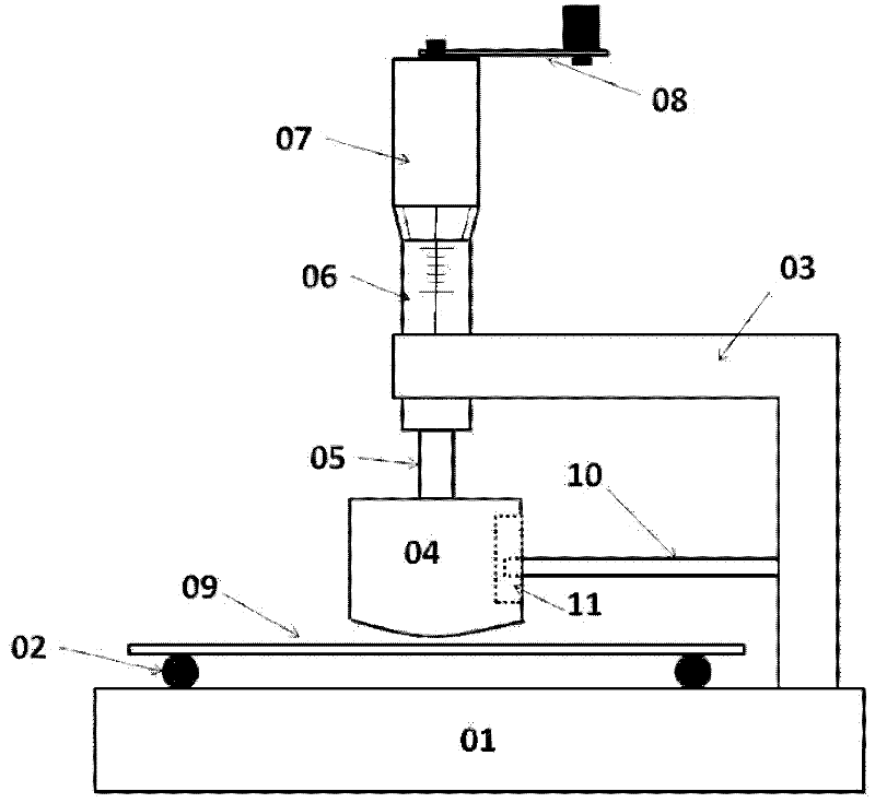
[0022] According to an embodiment of the present invention, there is provided a device for accurately bending a printed circuit board, including:

[0023] Base 01;

[0024] The two gaskets 02 on the base 01, the gasket 02 is cylindrical, and the two cylindrical gaskets are spaced apart and placed in parallel to carry the printed circuit board 09;

[0025] The micrometer includes a rotating part 07, a fixed part 06, and a shaft part 05 connected to the rotating part 07;

[0026] The fixed arm 03 is fixed to the base 01 and is used to fix the fixed part 06 of the micrometer. The fixed arm has a pillar 10 extending laterally from the fixed arm;

[0027] Rocker 08, rotatably fixed to the rotating part 07 of the micrometer;

[0028] The pressing block 04 is rotatably fixed to the shaft 05 of the micrometer. The pressing block has a longitudinal elongated groove 11 on the side close to the fixed arm 03, and one end of the pillar 10 extending laterally from the fixed arm extends into the concav...


PUM


Abstract

The invention provides a device for accurately bending a printed circuit board. The device comprises a base, a micrometer, a fixed arm and a pressing block, wherein two gaskets on the base are used for bearing the printed circuit board; the micrometer comprises a rotating part, a fixed part, and a shaft part which is linked with the rotating part; the fixed arm is fixed on the base and is used for fixing the fixed part of the micrometer; and the pressing block is fixed on the shaft part of the micrometer in a rotatable way.

Description

Technical field [0001] The invention relates to a device for accurately bending a printed circuit board. Background technique [0002] In recent years, due to the more and more progress of ceramic film overlay technology, the number of ceramic film overlay layers has increased, which has made the capacitance of multilayer ceramic capacitors higher and higher, and can gradually replace the low and medium capacitance aluminum electrolysis Capacitors and tantalum capacitors. Chip ceramic capacitors can be directly pasted through SMT, and the production speed is faster than aluminum electrolytic capacitors and tantalum capacitors. In addition, they have the characteristics of small size, stable temperature characteristics, and wide application range. [0003] Assessing the firmness of the bonding between the terminal electrode of the chip ceramic capacitor and the ceramic substrate is to subject the capacitor body and the substrate to be welded to a bending stress, and to monitor the ...

Claims


Application Information

Patent Timeline
IPC IPC(8): G01N19/04
Inventor 陈雁张伟王建国张延伟孙吉兴龚欣王旭段超刘豫东
Owner CHINA ACADEMY OF SPACE TECHNOLOGY
Why Eureka
Try Eureka