
Method for automatically detecting longitudinal tear of conveyor belt based on machine vision

A technology of longitudinal tearing and machine vision, applied in the detection of longitudinal tearing of conveyor belts, automatic detection of longitudinal tearing of conveyor belts based on machine vision, can solve problems such as longitudinal tearing of conveyor belts, and achieve the effect of simple identification methods

Active Publication Date: 2012-07-11
TIANJIN POLYTECHNIC UNIV +1
View PDF2 Cites 19 Cited by
  • Summary
  • Abstract
  • Description
  • Claims
  • Application Information

AI Technical Summary

Benefits of technology

This patented invented system uses an imaging device that captures images on the surface of the conveying material's transportation path during operation. It then analyzes these captured pictures to identify any signs or defects caused by damage to the materials being carried through it. These systems are able to recognize different types of tears without human interference while also providing automatic adjustment capabilities based upon environmental factors like brightness levels. Overall, this innovative solution allows for better maintenance control over industrial processes involving long distance conveyors such as manufacturing lines.

Problems solved by technology

This patented technical problem addressed in this patents relates to identifying or predicting when there may occur an abnormality called longterm tearing (LT) that could lead to breakage of conveyer belting during use for various industrial applications such as mineral processing plants where materials move along rails under gravity. Current methods require manual inspections with cameras while they work well, but these techniques cannot accurately identify any issues beforehand due to factors like vibrations caused by movement over uneven surfaces.

Method used


Image

  • Method for automatically detecting longitudinal tear of conveyor belt based on machine vision
  • Method for automatically detecting longitudinal tear of conveyor belt based on machine vision
  • Method for automatically detecting longitudinal tear of conveyor belt based on machine vision

Examples


Embodiment Construction

[0028] In order to better illustrate the purpose and advantages of the present invention, the present invention will be further described in detail below in conjunction with the accompanying drawings.

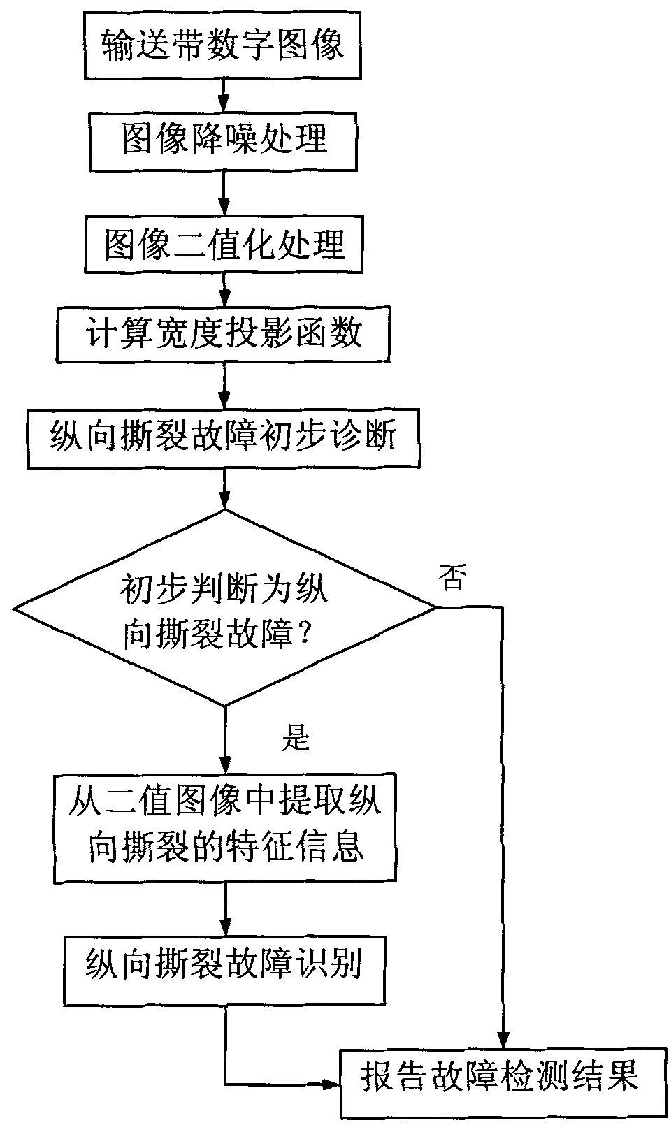
[0029] An automatic detection method for longitudinal tearing of conveyor belts based on machine vision, the overall technical scheme is as follows figure 1 As shown, it specifically includes the following steps:

[0030] Step 1, carrying out noise reduction processing on the conveyor belt digital image f(i, j), i

[0031] The noise reduction processing may be a combination of one or more methods of geometric processing, image filtering, image smoothing and image sharpening.

[0032] Step 2, on the basis of step 1, binarize the image of the conveyor belt after noise reduction to obtain a binary image g(i, j);

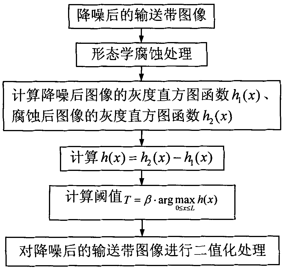
[0033] Described image binarization processing method such as figure 2 As shown, it specifically includes the following steps:

[0034] (1) Carry out graysc...


PUM


Abstract

The invention discloses a method for automatically detecting the longitudinal tear of a conveyor belt based on machine vision and belongs to the field of the monitoring of equipment status. The method comprises the following steps of: setting a binary threshold value according to the change of a gray histogram function of an image before and after morphological corrosion treatment so as to realize the separation of a target and a background, performing preliminary diagnosis on a longitudinal tear fault of the conveyor belt by designing a width projection function, extracting characteristic information of the longitudinal tear from a binary image after the longitudinal tear fault is preliminarily diagnosed, and further identifying the longitudinal tear fault of the conveyer belt by using the extracted characteristic information of the longitudinal tear. The method has an intelligent detection function, is suitable for on-line detection of longitudinal tear faults of conveyer belts, and is favorable for detecting the running state of the conveyer belts in real time by a machine vision technology.

Description


Claims


Application Information

Patent Timeline
Owner TIANJIN POLYTECHNIC UNIV
Learn More