Check patentability & draft patents in minutes with Patsnap Eureka AI!

Method and device for positioning on board units in electronic toll collection system

An electronic toll collection system and vehicle-mounted equipment technology, applied in the field of communication, can solve the problems of poor positioning accuracy and difficulty in accurately positioning OBU1 and OBU2, etc.

Active Publication Date: 2012-07-11
BEIJING WATCH DATA SYST
View PDF6 Cites 8 Cited by
  • Summary
  • Abstract
  • Description
  • Claims
  • Application Information

AI Technical Summary

Problems solved by technology

However, when using a long communication area, the OBU that completes the transaction first has poor positioning accuracy because it is far away from the gantry
For example, as attached figure 1 As shown, the RSU is equipped with receiving antenna 1, receiving antenna 2 and receiving antenna 3. At a distance of 6 meters from the gantry, for receiving antenna 3, due to the small horizontal main lobe beam projection range, the radio frequency emitted by OBU1 and OBU2 The power of the signal reaching the receiving antenna 3 is very different, and it is easy to accurately locate the positions of OBU1 and OBU2; and at a distance of 12 meters from the gantry, also for the receiving antenna 3, due to the larger projection range of the main lobe beam in the horizontal direction, OBU1 The power difference between the RF signal transmitted by OBU2 and the receiving antenna 3 is very small, so it is difficult to accurately locate the positions of OBU1 and OBU2

Method used


Image

  • Method and device for positioning on board units in electronic toll collection system
  • Method and device for positioning on board units in electronic toll collection system
  • Method and device for positioning on board units in electronic toll collection system

Examples


Embodiment Construction

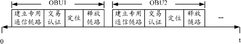
[0020] In the MLFF system, the traditional communication process between RSU and OBU is as attached figure 2 As shown, it can be divided into four steps: establishing a dedicated communication link, transaction authentication, OBU positioning and releasing the link. After the vehicle with the OBU installed enters the communication area of ​​the MLFF system, the OBU is awakened by the Beacon Service Table (BST) wake-up signal emitted by the RSU transmitting antenna, and the RSU establishes a dedicated communication link with the awakened OBU. After RSU and OBU have passed mutual authentication, and RSU writes the transaction result information into OBU, RSU sends a positioning indication signal to the OBU, and after receiving the positioning signal returned by the OBU, determines the positioning result and sends a link release to the OBU After receiving the link release signal, the OBU enters a dormant state, and will no longer respond to the signal transmitted by the same RSU...


PUM


Abstract

The invention discloses a method for positioning on board units (OBUs) in an electronic toll collection system, which is used for improving the positioning accuracy of the OBUs. The method comprises the following steps of: when a roadside unit (RSU) starts repositioning for the OBUs which have finished at least one time of positioning, comparing the last positioning time corresponding to each OBU with the current time; determining a set of the OBUs to be positioned, wherein the difference between the current time and the last positioning time of each OBU to be positioned is greater than a preset threshold value; sequentially sending positioning indicating signals to each OBU to be positioned in the set; when determining that a positioning signal returned by a random OBU to be positioned is received, determining and storing the current positioning record of the OBU to be positioned according to the positioning signal; otherwise, when determining that the positioning signal returned by the random OBU to be positioned is not received, determining a final positioning result according to the historical positioning record of the OBU to be positioned. The invention simultaneously discloses a device for positioning the OBUs in the electronic toll collection system.

Description

technical field [0001] The invention relates to the field of communication technology, in particular to a method and device for positioning vehicle equipment in an electronic toll collection system. Background technique [0002] In the existing multi-lane free flow (Multi Lane Free Flow, MLFF) charging system, the positioning function of the on-board unit (On Board Unit, OBU) is generally provided by the dedicated short-range communication module of the roadside unit (Roadside Unit, RSU). (Dedicated Short Range Communication, DSRC) to complete. When the DSRC module of the RSU installed on the driveway gantry receives the radio frequency signal transmitted by the OBU, it calculates and determines according to the difference in signal strength received by each DSRC module, combined with information such as the direction diagram and installation position of the radio frequency receiving antenna The location of the OBU. [0003] In order to increase the speed of vehicle traffi...

Claims


Application Information

Patent Timeline
IPC IPC(8): G07B15/06
Inventor 孙晓会裴世兵
Owner BEIJING WATCH DATA SYST
Features
  • R&D
  • Intellectual Property
  • Life Sciences
  • Materials
  • Tech Scout
  • Unparalleled Data Quality
  • Higher Quality Content
  • 60% Fewer Hallucinations
Learn More