
Tension constant resistor capable of calculating difference of alternating current and direct current

A technology of AC-DC difference and tension, applied in the direction of resistor installation/support, helical coil/screw disk resistance element, etc., can solve the problems of poor stability of AC-DC difference resistance, affect the accurate calculation of parasitic inductance, etc., and achieve the goal of improving stability Effect

Active Publication Date: 2012-07-11
BEIJING DONGFANG MEASUREMENT & TEST INST
View PDF3 Cites 4 Cited by
  • Summary
  • Abstract
  • Description
  • Claims
  • Application Information

AI Technical Summary

Problems solved by technology

However, the hanging wire structure in which the resistance wire is suspended at the center of the coaxial line, due to the effect of stress release, the difference in expansion coefficient between the inner and outer cylinders and the resistance wire, and external force, will cause the resistance wire to relax as time goes by. Phenomenon, can not always maintain a tight state, which affects the accurate calculation of parasitic inductance and parasitic capacitance and various additional losses, resulting in poor stability of this calculable AC-DC differential resistance
At the same time, the resistance wire and the bottom of the inner cylinder, and the resistance wire and the positive end of the potential are usually connected by welding, which can generate thermal potential and cause AC and DC to deteriorate

Method used


Image

  • Tension constant resistor capable of calculating difference of alternating current and direct current
  • Tension constant resistor capable of calculating difference of alternating current and direct current
  • Tension constant resistor capable of calculating difference of alternating current and direct current

Examples


Embodiment Construction

[0023] Embodiments of the present invention will be described in further detail below in conjunction with the accompanying drawings.

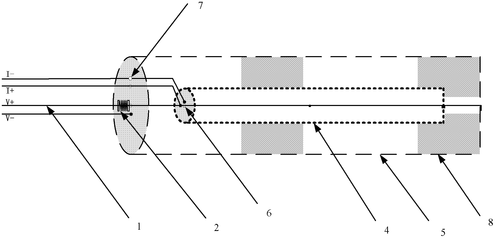
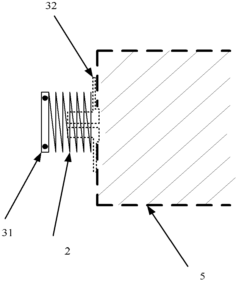
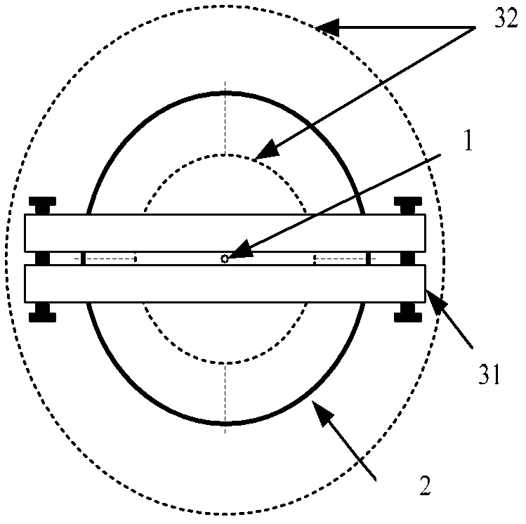
[0024] Such as figure 1 As shown, a constant tension AC-DC difference resistance can be calculated, including a coaxial inner metal sleeve 4 and an outer metal sleeve 5, the resistance wire 1 is located on the central axis of the inner metal sleeve 4, from the resistance wire 1 Lead out the current positive terminal lead-out line I+ and the voltage positive terminal lead-out line V+, draw the current negative terminal lead-out line I- from the front end face of the inner metal sleeve 4, and draw the voltage negative end lead-out line from the front end face of the outer metal sleeve 5 V-; the center of the front end of the inner metal sleeve 4 and the outer metal sleeve 5 respectively has a front center hole 6, and the resistance wire 1 passes through the center hole of the front end of the inner metal sleeve and the center of the front end of ...


PUM


Abstract

The invention provides a tension constant resistor capable of calculating difference of alternating current and direct current, which is applicable to a coaxial-line hang-spring structure and is provided with a tension device enabling a resistance wire to keep in a tight state all the time. The tension constant resistor improves the stability of a resistor structure capable of calculating the alternating current and the direct current. The tension constant resistor comprises an inner metal sleeve and an outer metal sleeve which are coaxial, a mono-wire linear resistance wire is located in the central axial of the inner metal sleeve, the resistance wire adopts a duel-hole return wire method to be connected with a back end face of the inner metal sleeve and then to be connected with the a back end face of the outer metal sleeve in a pressure welding mode. A front end face center hole is respectively arranged in the central positions of front end faces of the inner metal sleeve and the outer metal sleeve, the resistance wire sequentially penetrates through the front end face center holes of the inner metal sleeve and the front end face center hole of the outer metal sleeve, and the tension device enabling the resistance wire to keep in the tight state is arranged at the position where the resistance wire penetrates from the front end face center hole of the outer metal sleeve.

Description

technical field [0001] The invention relates to the technical field of electrical measurement, in particular to a calculable AC / DC differential resistance with constant tension. Background technique [0002] Resistors are one of the most common electrical components. High-precision resistors are not only the core components of high-precision instruments, but also widely used in many scientific research occasions. In order to improve the accuracy of resistance value, since 1990, the international metrology community has successively started research on replacing traditional physical resistance standards with quantized Hall resistance standards. Experiments have proved that after adopting the quantized Hall resistance standard, the recurrence accuracy and international consistency of the value of the resistance unit are improved by more than 2 orders of magnitude compared with the physical measurement benchmark, and it fundamentally eliminates the change in the value of the re...

Claims


Application Information

Patent Timeline
Patent Type & Authority Applications(China)
IPC IPC(8): H01C3/14H01C1/01
Inventor 黄晓钉罗宇轩潘攀
Owner BEIJING DONGFANG MEASUREMENT & TEST INST
Learn More