Inductance element

A technology of inductance components and components, applied in the field of inductance components, can solve the problems of increasing the temperature of the magnetic core and decreasing the current allowable value, and achieve the effect of improving the strength of soldering

Active Publication Date: 2015-03-25
ALPS ALPINE CO LTD
View PDF9 Cites 0 Cited by
  • Summary
  • Abstract
  • Description
  • Claims
  • Application Information

AI Technical Summary

Problems solved by technology

As a result, the temperature of the magnetic core becomes high, and the allowable value of the current flowing through the coil body tends to decrease.

Method used


Image

  • Inductance element
  • Inductance element
  • Inductance element

Examples


Embodiment Construction

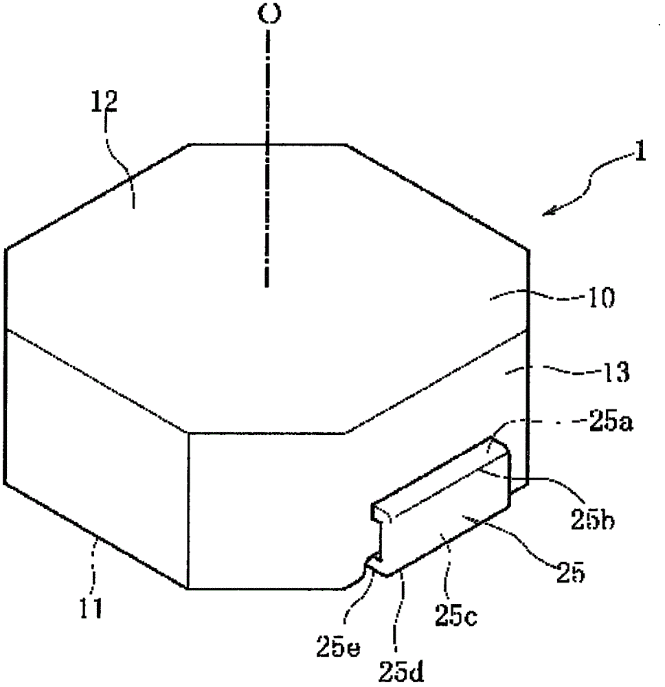
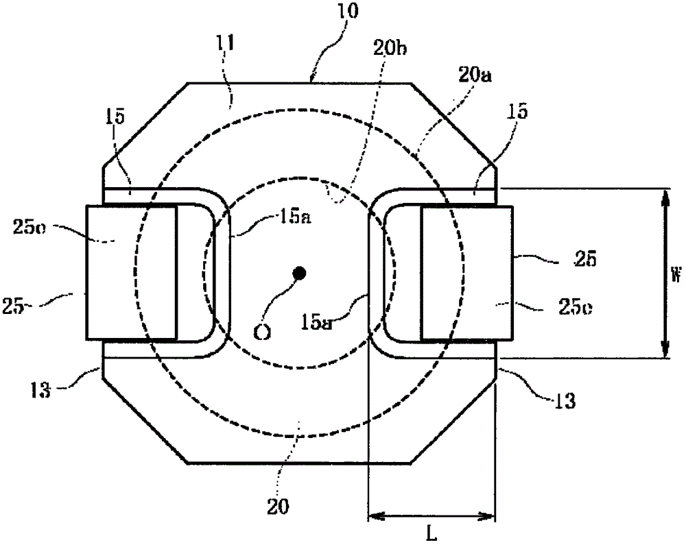
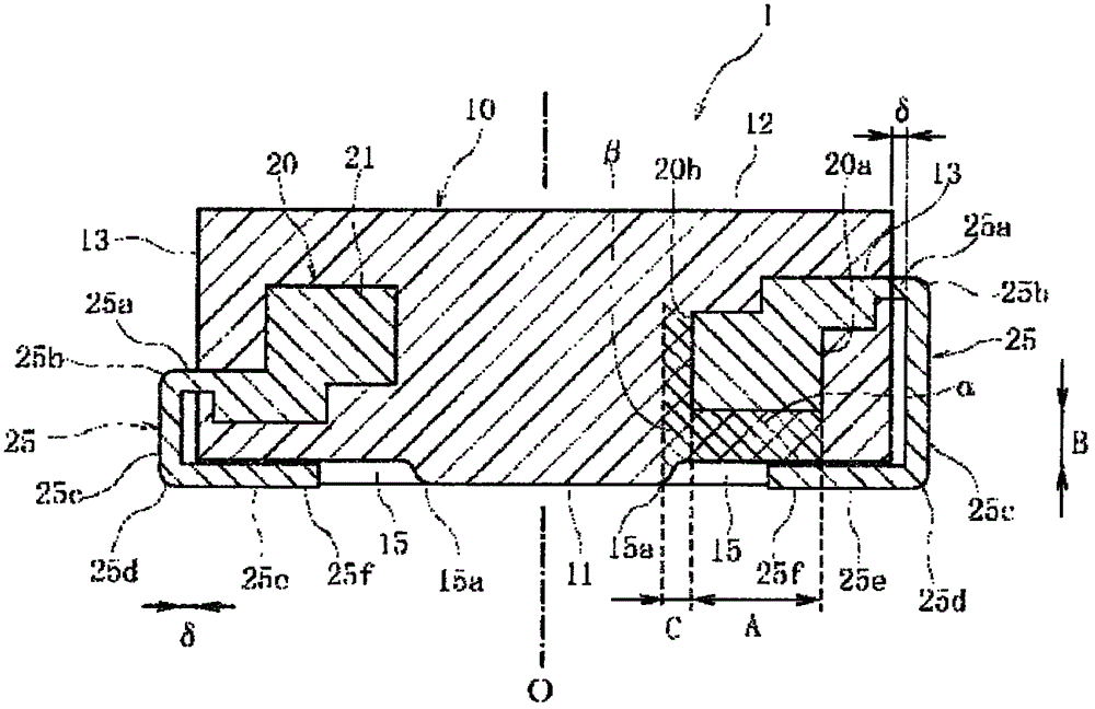
[0047] Figure 1 to Figure 3 In the illustrated inductance element 1 , a coil body 20 is embedded in a magnetic core 10 . A pair of terminal plates 25 , 25 are connected to the coil body 20 , and the terminal plates 25 , 25 extend to the outside of the magnetic core 10 .

[0048] The magnetic core 10 has a bottom surface 11 and an upper surface 12, and the bottom surface 11 and the upper surface 12 are parallel to each other. Such as figure 2 As shown, the shape of the magnetic core 10 viewed from the bottom surface 11 side is an octagon. The terminal boards 25 , 25 extend from the side surfaces 13 , 13 that are parallel to each other among the eight side surfaces. exist Figure 1 to Figure 3 In , a line extending perpendicular to the bottom surface 11 and the upper surface 12 of the magnetic core 10 and passing through the center of the octagon is represented by a centerline O.

[0049] Furthermore, the planar shape of the magnetic core 10 may be a square, a rectangle, ...


PUM

PropertyMeasurementUnit
densityaaaaaaaaaa

Abstract

The invention provides an inductance element, wherein a bottom part of a magnetic core is configured with a concave part of a terminal plate. In the inductance element, the decrease of the inductance of the concave part can be suppressed. A coil body (20) is embedded in the magnetic core (10), namely a collection body of the magnetic powder. A bottom surface of the magnetic core (10) is provided with a concave part (15,15) of the terminal plate (25,25) extending from the coil body (20), and the step difference between the surface of the terminal plate (25,25) and the bottom surface of the magnetic core (10). The density of the magnetic powder of the magnetic core (10) in an area between the concave part (15) and the coil body (20), thereby the magnetic flow of the area can be improved. Therefore the inductance decrease aused by the concave part (15) can be suppressed.

Description

technical field [0001] The present invention relates to an inductance element in which a coil body is embedded in a magnetic core formed by compressing magnetic powder, and a concave portion for accommodating a terminal plate is formed on the bottom surface of the magnetic core. Background technique [0002] The following Patent Documents 1 to 3 disclose an inductance element in which a coil body is embedded in a magnetic core. The magnetic core is a so-called dust core formed by compressing magnetic powder. The magnetic powder is a magnetic alloy powder, and the magnetic powder coated with an insulating resin is compressed to form the magnetic core. [0003] In this inductance element, a terminal plate extending from the coil body protrudes from the side surface of the magnetic core, and is bent toward the bottom surface of the magnetic core, and the surface of the terminal plate is provided substantially parallel to the bottom surface of the magnetic core. [0004] (Prio...

Claims


Application Information

Patent Timeline
Patent Type & Authority Patents(China)
IPC IPC(8): H01F27/29H01F17/04
Inventor 安彦世一荒木庆一松山英一郎水岛隆夫
Owner ALPS ALPINE CO LTD
Why Eureka
Try Eureka