
Anti-waterlogging distribution box and buried transformer station with same

A technology for buried substations, applied in closed substations, substations, substations/distribution device shells, etc., can solve the problems of insufficient load reduction, inability to prevent flood disasters, and difficulty in ensuring sealing quality, etc., to achieve power supply Safe and effective protection, blocking external floods, and saving installation space

Active Publication Date: 2012-07-11
基元电气有限公司
View PDF8 Cites 4 Cited by
  • Summary
  • Abstract
  • Description
  • Claims
  • Application Information

AI Technical Summary

Problems solved by technology

[0006] The existing power distribution methods mainly include power distribution rooms, European-style box-type transformers, and American-style box-type transformers. These power distribution equipment have the following defects: that is, in the case of flooding, water will enter the interior from the gap in the transformer shell, and the The components of the transformer are soaked in water, which makes the transformer unable to operate normally; although underground transformers that can meet the requirements of submerged operation have appeared, the high and low voltage power distribution cabinets of underground transformers, or power distribution rooms, European box transformers and The high and low voltage power distribution cabinets of American-style box-type substations cannot meet the requirements for preventing floods where the water level exceeds the surface
[0007] However, this regulation only ensures that the substation can work normally when the water level of the flood does not exceed the ground level. When the actual flood disaster occurs, it is very common that the water level of the flood exceeds the ground level. The power supply security of the station cannot be effectively guaranteed
[0008] In addition, there is also a method of fully sealing the power distribution cabinet to prevent waterlogging. This kind of full sealing method is to install a closed shell outside the power distribution cabinet. However, it has the following disadvantages: (1) in the power distribution cabinet The power distribution components will dissipate heat during operation, but the sealed casing cannot be ventilated and dissipated; (2) The power distribution equipment needs to be installed and connected with the power supply network and the power load, and the site construction is very large, and the fully sealed method requires precise , Professional construction operations, however, this part of the work is completed by the construction personnel on site, therefore, the sealing quality is difficult to guarantee; (3) The power distribution equipment needs to carry out various maintenance and repair and replacement of power distribution components during its operation, but The fully sealed method has no good measures for cable replacement, increase and decrease of load quantity, and the user units of each power distribution equipment generally do not have existing sealing materials and professional operators with sealing knowledge, so the power distribution equipment is in use. (4) The sealing process at the connection point of the fully sealed structure is very complicated, which makes the reliability of the sealing material not high. At the same time, it is affected by the construction conditions, construction environment and on-site use environment. After 3 to 5 years, the sealing material needs to be inspected and replaced. Affected by the use and inspection personnel, many hidden dangers of leakage cannot be completely eliminated.

Method used


Image

  • Anti-waterlogging distribution box and buried transformer station with same
  • Anti-waterlogging distribution box and buried transformer station with same
  • Anti-waterlogging distribution box and buried transformer station with same

Examples


Embodiment Construction

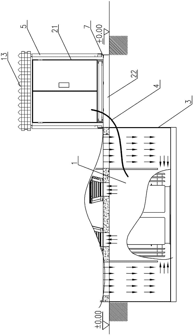
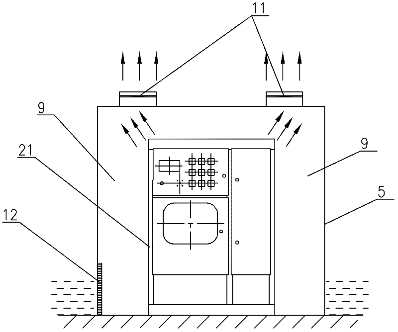
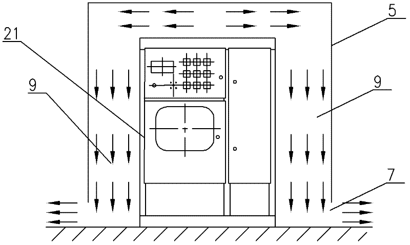
[0040] Such as Figure 1~3 As shown, it is a flood control buried substation of the present invention, including an underground transformer 1 that can be submerged in water, a power distribution cabinet, and a prefabricated pit foundation 3. The underground transformer 1 is arranged in the prefabricated pit foundation 3, and the underground The terminals of the type transformer 1 are connected to the power distribution cabinet through cables 4, wherein the power distribution cabinet includes a power distribution cabinet body 21 and a power distribution foundation 22 for installing the power distribution cabinet body 21, and the power distribution foundation 22 is higher than the ground surface The platform is equipped with a waterproof cover 5 outside the power distribution cabinet. The waterproof cover 5 is made of rigid materials. The waterproof cover 5 is a three-dimensional container with an opening on the bottom surface that is adapted to the contour of the power distribut...


PUM


Abstract

The invention discloses an anti-waterlogging distribution box capable of preventing flood disaster and guaranteeing electricity utilization, which comprises a distribution box body and a distribution foundation. The distribution box body is arranged on the distribution foundation, the distribution foundation is a platform which is higher than surface of earth, a waterproof cover is arranged outside the distribution box, the waterproof cover is a three-dimensional container with an opening at the bottom surface, contour of the waterproof cover is matched with that of the distribution box body, the waterproof cover covers the distribution box, so that the distribution box is positioned inside an inner cavity of the waterproof cover, and the bottom of the waterproof cover is provided with a water inlet channel. When water level exceeds the distribution foundation during flood, the bottom of the waterproof cover serves as the water inlet channel of the waterproof cover. The waterproof cover forms a sealed space after the opening of the waterproof cover is submerged by water. The invention also discloses a buried transformer station with the anti-waterlogging distribution box. The waterproof cover forms the sealed space when water enters the waterproof cover. When air pressure in the sealed space is equal to sum of external atmospheric pressure and water pressure, the water level in the waterproof cover maintains at a certain level and stops rising. Therefore, external flood is held back and the distribution box is capable of operating while being immersed in water.

Description

technical field [0001] The invention relates to a power distribution system, in particular to a waterlogging-proof power distribution box and an underground substation equipped with the power distribution box, which can still ensure the safety of power consumption under natural disasters such as floods and waterlogging. Background technique [0002] The traditional substation is built on the ground level. Since the substation requires a special building structure, it is huge in size and needs to reserve a large installation space during construction. It may occupy the installation position of other necessary facilities, so its installation conditions are limited. Certain restrictions, and the appearance of the substation is relatively monotonous, which will destroy the beauty of the landscape of the community, affect the overall planning of the garden of the community, and make it unable to meet the needs of urban beautification and urban cultural construction. [0003] Base...

Claims


Application Information

Patent Timeline
IPC IPC(8): H02B1/28H02B7/08H02B1/56
Inventor 冯骏明梁军
Owner 基元电气有限公司
Learn More