Load fault diagnosis detection method and device thereof

A fault diagnosis and detection device technology, applied in the direction of measuring devices, measuring electricity, measuring electrical variables, etc., can solve problems such as indistinguishable short-circuit faults, inconsistency between output and expected value, short circuit between turns of inductance, etc., to improve protection and control reliability , the effect of preventing the further spread of faults

Active Publication Date: 2012-07-11
CHINA FIRST AUTOMOBILE
View PDF5 Cites 40 Cited by
  • Summary
  • Abstract
  • Description
  • Claims
  • Application Information

AI Technical Summary

Problems solved by technology

Usually, the hardware system drives the pulse width without feedback signal, that is, it only performs open-loop control. However, when the actual controller processes the signal, if the output control pulse width task encounters a higher priority task during execution, the lower priority task will be controlled by the system. Temporarily "hanging", which will cause the actual output to be inconsistent with the expected value. If the difference is within a certain range, the impact on system performance will be small, but if the gap between the actual output pulse width and the expected value is large, it may affect system performance. Therefore, it is necessary to judge whether the difference between the actual output pulse width and the expected value is within the acceptable range during the load driving process, so as to monitor whether the system performance is normal
[0006] From the above analysis, it can be seen that many patents have been involved in the detection of short-circuit and open-circuit faults, but for short-circuit faults, it is usually impossible to distinguish whether it is a short-circuit to the power supply or a short-circuit to the ground. , Welding point performance degradation, etc. These will lead to changes in load electrical parameters, and parameter changes beyond a certain range will directly affect performance. Therefore, it is necessary to be able to judge whether the load has an over-limit fault during the load driving process.

Method used


Image

  • Load fault diagnosis detection method and device thereof
  • Load fault diagnosis detection method and device thereof
  • Load fault diagnosis detection method and device thereof

Examples


Embodiment Construction

[0048] The working principle, specific structure and preferred embodiments of the load fault diagnosis and detection method and device of the present invention will be described in detail below in conjunction with the accompanying drawings.

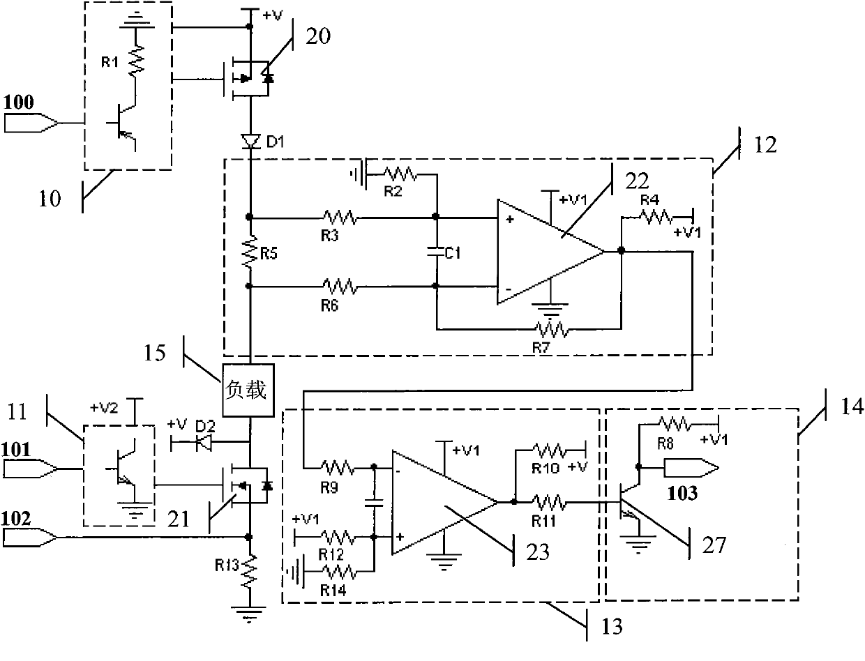
[0049] figure 1 It is a schematic block diagram of the load fault diagnosis and detection device of the present invention, which includes a high-end field effect transistor (MOSFET) pre-driver circuit 10, a high-end sampling resistor R5, a drive MOSFET pre-driver circuit 11, a low-end sampling resistor R13, and a signal differential amplifier circuit 12. Comparing circuit 13 and inverting circuit 14 are composed. The high-end MOSFET pre-driver circuit 10 is controlled by the signal 100 to realize the drive control of the high-end field effect transistor 20 and play the role of loading and disconnecting the load driving power supply +V.

[0050] The anode of the diode D1 is connected to the signal output of the high-end field effect trans...


PUM


Abstract

The invention relates to a load fault diagnosis detection method and a device thereof. Rise phase current waveform sampling is driven through a load, comparison with a preset threshold is carried out, logic overturn of a diagnosis signal which exceeds the threshold occurs, a time of a logic overturn moment of the diagnosis signal is detected, the time and a preset benchmark value are contrasted and analyzed, hereby whether the load has short circuit, circuit break and load over-limit faults is determined, and simultaneously, whether the short circuit fault is short circuit to ground or short circuit to a power supply can be determined; through measuring time of drive starting moment and ending moment of diagnosis signal overturn, comparison with a driving signal is carried out, and hereby whether pulse width output of the driving signal has abnormity or not is determined. According to the method, only a diagnosis circuit is added based on a load performer driving circuit, additional cost is low, protection and control reliability in a load performer driving process can be raised substantially, and a foundation for load driving analysis and fault diagnosis is established.

Description

technical field [0001] The invention relates to a load fault diagnosis and detection method and device, which can be used in the related technical field of load driving of an electric control system. Background technique [0002] In electronically controlled vehicles and engine systems, there are various load actuators, such as solenoid valves, motors, relays, etc. These load actuators are the core components of the entire electronic control system, and the performance of the actuators directly affects the performance of the vehicle and Engine performance, especially for fuel injection system actuators, will directly affect engine and vehicle functions. Therefore, it is necessary to detect its performance in real time during the driving process of the load actuator. Once the abnormal function is abnormal, the program will perform corresponding fault handling and protection to prevent the fault from spreading further. [0003] The drive of the load actuator is mainly based o...

Claims


Application Information

Patent Timeline
Patent Type & Authority Applications(China)
IPC IPC(8): H02H3/08G01R31/02
Inventor 宋国民朱晓明
Owner CHINA FIRST AUTOMOBILE
Why Eureka
Try Eureka