Single-power-supply positive and negative logic conversion circuit

A positive and negative logic and conversion circuit technology, which is applied in the direction of logic circuit connection/interface layout, logic circuit coupling/interface using field effect transistors, etc., can solve the problem of increasing chip cost, increasing the difficulty of power supply wiring, and cumbersome positive and negative logic conversion circuits and other problems, achieving the effect of simple logic conversion circuit and reducing chip cost

Active Publication Date: 2012-07-11
WUXI I-MENG ELECTRONIC TECH CO LTD
View PDF4 Cites 4 Cited by
  • Summary
  • Abstract
  • Description
  • Claims
  • Application Information

AI Technical Summary

Problems solved by technology

[0003] The existing positive and negative logic conversion circuit technology has the following disadvantages: one is that two positive and negative power supplies are required, which not only incr...

Method used


Image

  • Single-power-supply positive and negative logic conversion circuit
  • Single-power-supply positive and negative logic conversion circuit
  • Single-power-supply positive and negative logic conversion circuit

Examples


Embodiment Construction

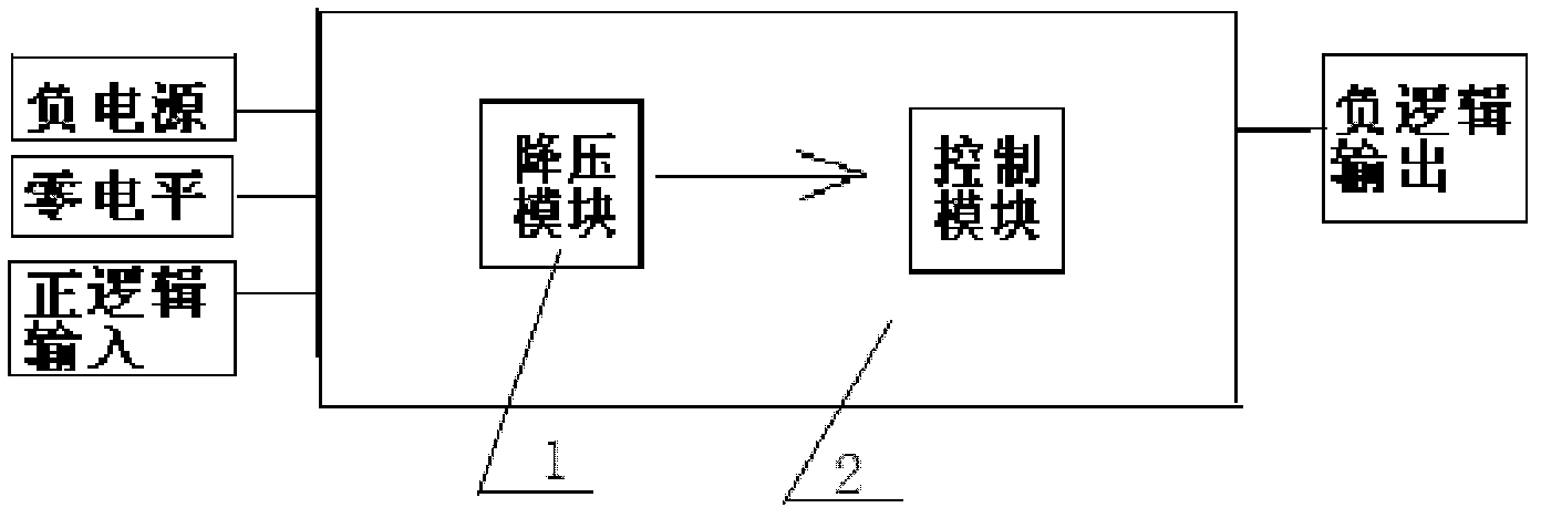
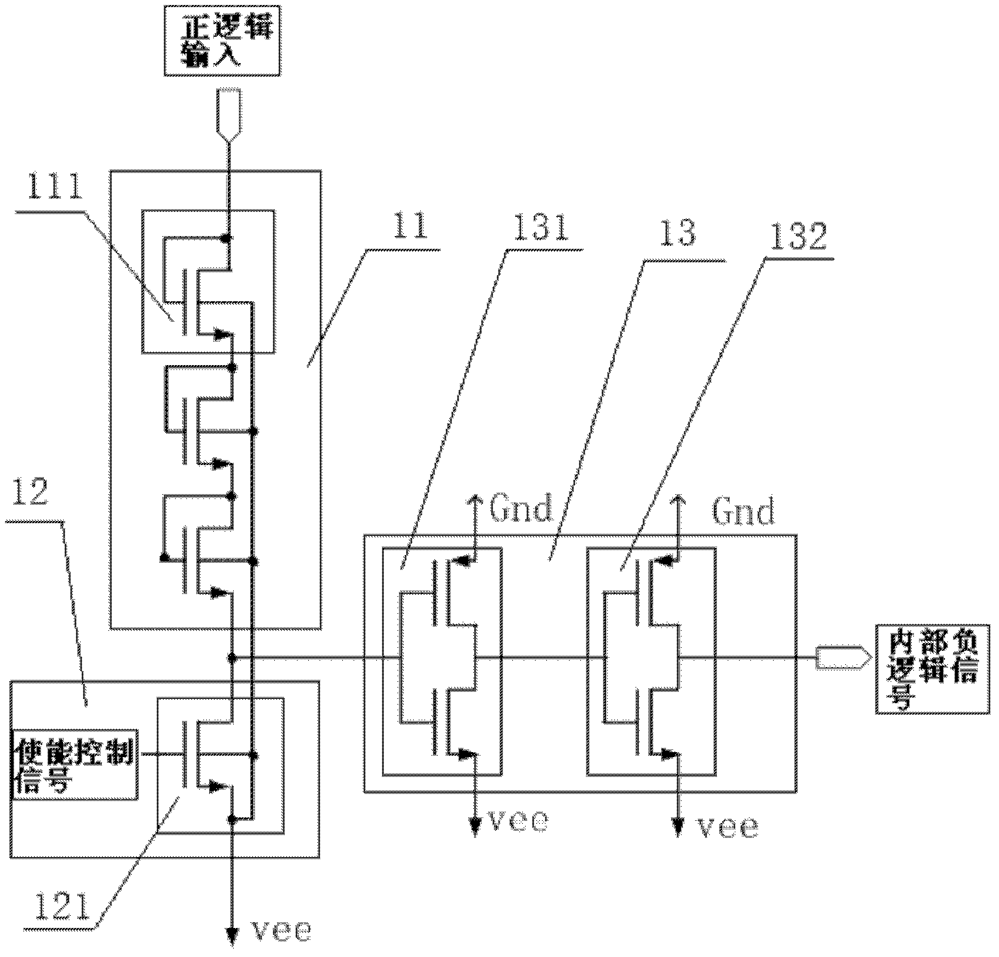
[0018] Such as figure 2 , image 3 , Figure 4 Shown is a schematic structural diagram of a single power supply positive and negative logic conversion circuit, a schematic structural diagram of a step-down module, and a schematic structural diagram of a step-down module in an embodiment of the present invention.

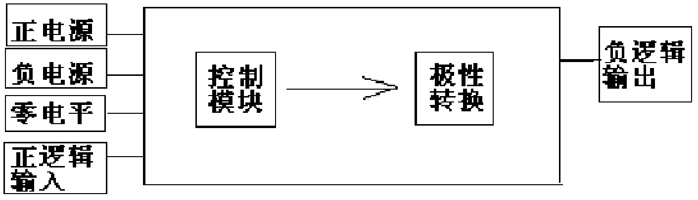
[0019] A single power supply positive and negative logic conversion circuit, including power supply, zero level, positive logic input, control circuit 2, and negative logic output, the power supply only includes negative power supply; the control circuit 2 includes a step-down module 1 and a control module.

[0020] in Figure 4 It is a schematic diagram of the structure of the step-down module in the embodiment taking the 1.2um MOS process platform as an example.

[0021] Three NMOS transistors 111, 112, and 113 are directly connected in series behind the positive logic input signal, and the width-to-length ratio of the NMOS transistor 1 is 25 / 2.

[0022] The e...


PUM


Abstract

The invention discloses a single-power-supply positive and negative logic conversion circuit, which comprises a power supply, a zero level, a positive logic input, a control circuit and a negative logic output, wherein the power supply only comprises a negative power supply; the control circuit comprises a voltage reducing module and a control module; the voltage reducing module comprises an MOS (Metal Oxide Semiconductor) tube voltage reducing module and an enabling control module; the output end of the MOS tube voltage reducing module is connected with a reshaping and amplifying circuit through a signal; the MOS tube voltage reducing module is formed by connecting a plurality of NMOS (N-channel Metal Oxide Semiconductor) tubes in series; the enabling control module consists of one NMOS tube; the input end of the MOS tube voltage reducing module is connected with the positive logic input; the output end of the MOS tube voltage reducing module is connected with the input end of the enabling control module and an internal negative logic signal; the output end of the enabling control module is connected with a negative level; and the internal negative logic signal is connected with the input end of the control module. The single-power-supply positive and negative logic conversion circuit has the advantages that: only a single power supply is required for supplying power, the chip cost and the wiring difficulty and cost of a power wire are reduced, and the entire logic conversion circuit is relatively simple.

Description

technical field [0001] The invention relates to a positive-negative logic conversion circuit in the field of integrated circuits, in particular to a positive-negative logic conversion circuit under a single power supply state. Background technique [0002] With the development of electronic technology, positive and negative logic conversion circuits are often used in practical applications in the field of integrated circuits. Such as figure 1 Shown is a schematic structural diagram of an existing dual power supply positive and negative logic conversion circuit. It can be seen from the figure that both positive and negative logic conversion circuits are powered by dual power supplies, that is, a positive power supply and a negative power supply. Generally speaking, the input is often positive voltage logic, while the output is negative voltage logic, and the circuit realizes the conversion of positive and negative logic through a polarity conversion circuit. [0003] The ex...

Claims


Application Information

Patent Timeline
IPC IPC(8): H03K19/0185
Inventor 吴海宏王勇孙锋张勇曹发兵陈钟鹏丛红艳
Owner WUXI I-MENG ELECTRONIC TECH CO LTD
Why Eureka
Try Eureka