Method and device for optimizing load balancing

A load balancing and load technology, applied in the field of communication, can solve problems such as poor signal quality and ping-pong switching, and achieve the effect of reducing load and avoiding ping-pong switching

Inactive Publication Date: 2012-07-11
ZTE CORP
View PDF4 Cites 11 Cited by
  • Summary
  • Abstract
  • Description
  • Claims
  • Application Information

AI Technical Summary

Problems solved by technology

However, there is a problem. For cells with the same coverage or inclusion relationship, the cells with high load generally achieve high load because of their good signal quality and the large number of users accessing them. Cells with low load in the same geographical location often The signal quality is poorer than that of a high-load cell
Then, in order to achieve load balancing, after the UE selected by service priority switches to a low-load cell, it is likely to switch back to a high-load cell immediately because of poor signal quality, that is, a ping-pong handover occurs

Method used


Image

  • Method and device for optimizing load balancing
  • Method and device for optimizing load balancing
  • Method and device for optimizing load balancing

Examples


Embodiment 1

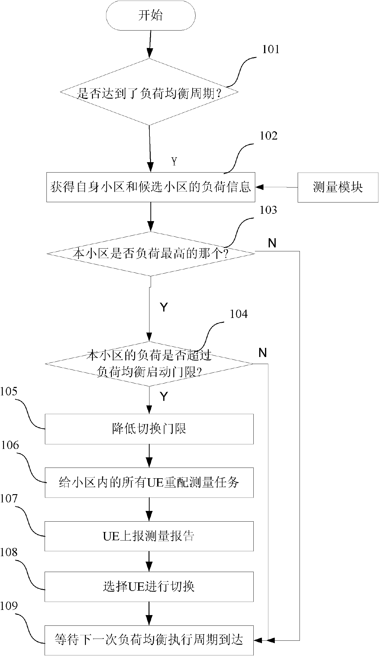
[0048] Such as figure 1 As shown, the embodiment of the present invention includes the following steps:

[0049] In step 101, the eNB judges whether the load balancing period is reached, and if so, proceeds to the next step;

[0050] Step 102, the eNB obtains the load status of the cell under its jurisdiction (hereinafter referred to as the cell) through the measurement module; and obtains the load information of the adjacent cell through the resource status report information of the adjacent cell sent by the base station of the adjacent cell;

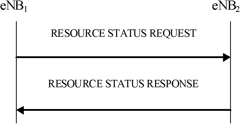
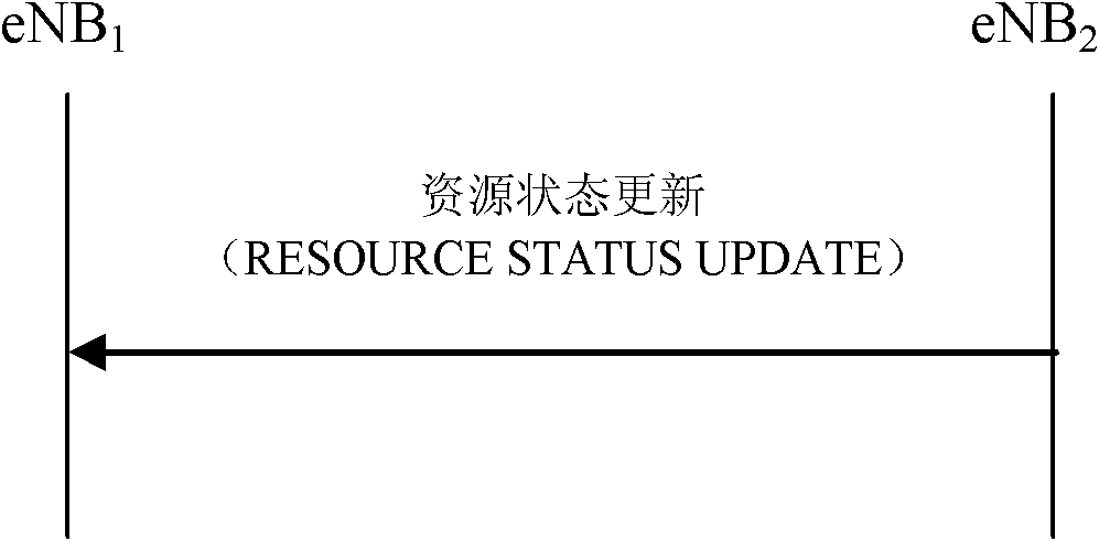
[0051] Among them, such as figure 2 and image 3 As shown, the neighbor cell load information is obtained through the X2 interface.

[0052] see figure 2 , eNB1 sends a resource status request message (RESOURCE STATUS REQUEST) to the base station eNB2 to which the neighboring cell belongs;

[0053] eNB2 returns a resource status response message (RESOURCE STATUSRESPONSE) to eNB1

[0054] see image 3 , eNB2 sends a resource st...

Embodiment 2

[0070] Steps 201-205 are the same as steps 101-105 in Embodiment 1.

[0071] In step 206, the first embodiment is improved, and some UEs are selected according to service priorities, and measurement tasks are reconfigured for the selected UEs.

[0072] Steps 207-209 are the same as steps 107-109 in Embodiment 1.

Embodiment 3

[0074] In the second example, since the number of UEs selected according to the service priority is limited, even if the handover threshold is lowered, there may be no UE that can meet the handover condition. Implementation example three improves example two.

[0075] Steps 301-305 are the same as steps 101-105 in Embodiment 1.

[0076] Step 306, select some UEs according to the service priority, and reconfigure measurement tasks for the selected UEs;

[0077] Step 307, if the measurement report is not received within a short period of time, expand the set of UEs selected according to the service priority in step 306, or lower the handover threshold again, resend the measurement task, and repeat step 307 until the UE that meets the handover conditions is selected , to switch;

[0078] Step 308, waiting for the arrival of the next load balancing execution period.

[0079] It should be noted that in this embodiment:

[0080] 1. The switching threshold cannot be lowered too l...


PUM


Abstract

The invention discloses a method and device for optimizing load balancing. The method comprises the steps of: when judging that a cell of an eNB (evolved Node) needs to be subjected to load balancing by the eNB, selecting all the UEs (User Equipment) or part of UEs in the cell, and adjusting threshold parameters of switching events, then sending the threshold parameters to the selected UEs; and according to measurement reports and load condition of the cell reported by the UEs, selecting one or more UEs for switching by the eNB. According to the method, while the load of a source cell is reduced, the signal quality after the switched UEs are switched to a target cell can be guaranteed, so that the ping-pong switching is avoided, and the UEs unnecessarily must be switched to a cell of the same coverage or inclusion relation.

Description

technical field [0001] The present invention relates to the communication field, in particular to a method and device for optimizing load balancing in an LTE (Long Term Evolution, long-term evolution) system. Background technique [0002] Load balancing is a method to prevent excessive load in individual cells. It can distribute the load as evenly as possible among geographically related cells and reduce the concentration of load in a certain cell in the area, thereby effectively improving the overall performance of the system. Improve the security, stability and capacity of the system, so that the system can reach an overall optimal state. [0003] The process of load balancing generally includes three stages: measurement stage, judgment stage and execution stage. The measurement stage is mainly to measure the load situation in the cell, and at the same time obtain the load information of the adjacent cell (including the same coverage and inclusion relationship) through th...

Claims


Application Information

Patent Timeline
Patent Type & Authority Applications(China)
IPC IPC(8): H04W28/08H04W36/08H04W36/30
CPCH04W36/22H04W28/08H04W28/0862
Inventor 卫建国朱永升
Owner ZTE CORP
Why Eureka
Try Eureka