
Valve having a magnet bag

A technology of valve needle and valve core, which is applied in the field of valves with magnetic stacks, can solve problems such as high cost, and achieve the effects of improved dynamics, fast switching, and high dynamics

Inactive Publication Date: 2012-07-11
ROBERT BOSCH GMBH
View PDF6 Cites 0 Cited by
  • Summary
  • Abstract
  • Description
  • Claims
  • Application Information

AI Technical Summary

Problems solved by technology

[0005] Although it has been proposed to replace the electromagnetic drive in the valve with a piezoelectric drive in order to further improve the dynamics, this solution is only economical under certain conditions due to the significantly higher costs of the piezoelectric drive

Method used


Image

  • Valve having a magnet bag
  • Valve having a magnet bag
  • Valve having a magnet bag

Examples


Embodiment Construction

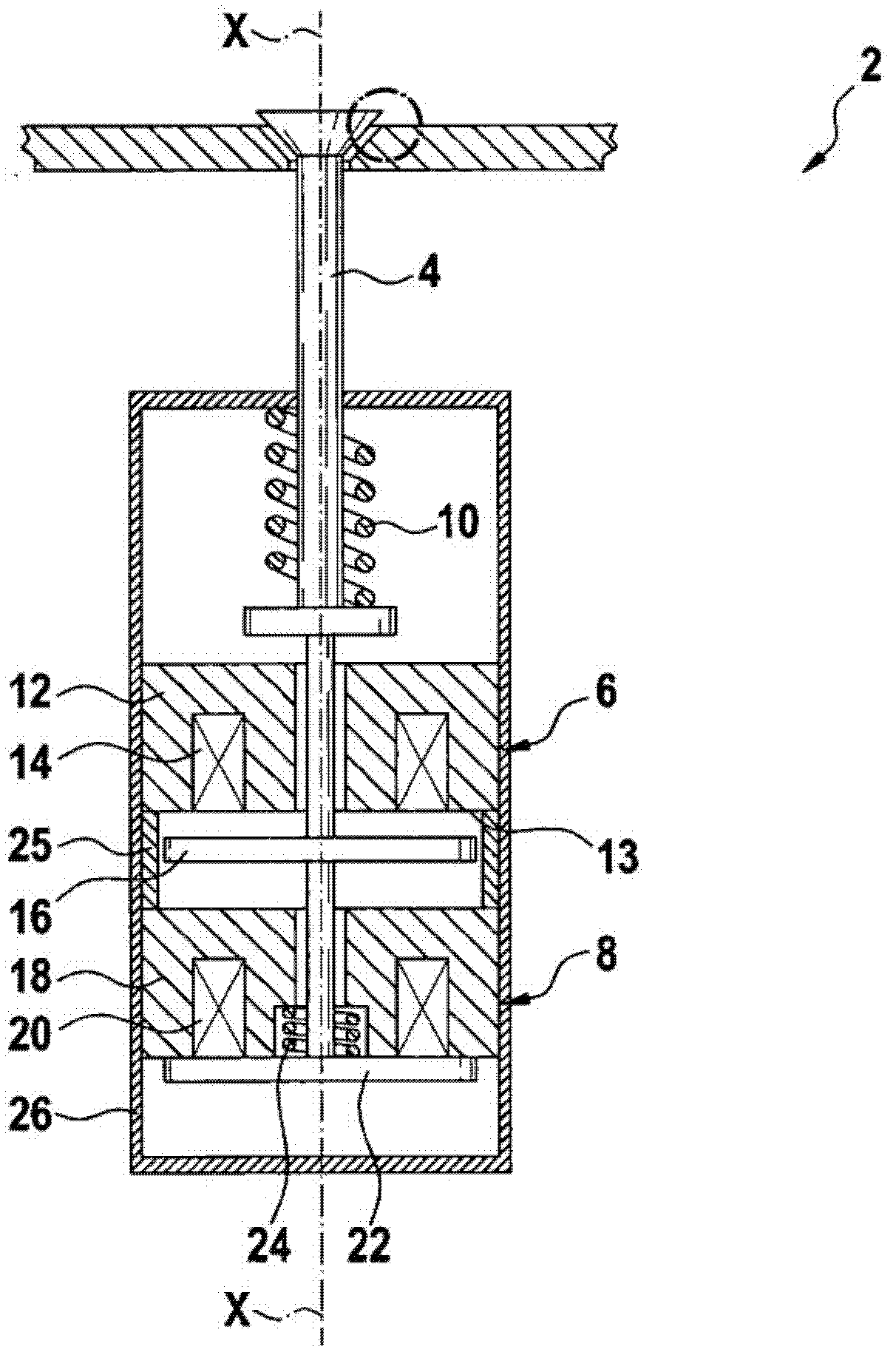
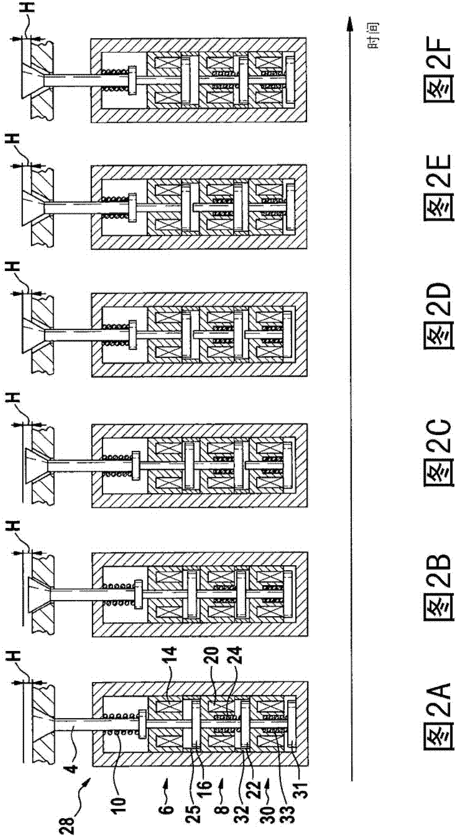
[0032] FIG. 1 shows a first embodiment of a valve 2 according to the invention with a two-stage valve stack. Such a valve 2 can be used, for example, as an injection valve in an internal combustion engine. The valve 2 has a valve needle 4 , a first electromagnetic drive 6 and a second electromagnetic drive 8 . The first electromagnetic drive 6 is provided for direct actuation of the valve needle 4 , while the second electromagnetic drive 8 actuates the valve needle via the first electromagnetic drive 6 . The first and second electromagnetic drives 6 , 8 can be moved back into the zero position by means of the main return spring 10 .

[0033] The first electromagnetic drive 6 has a first magnetic circuit 12 , a first coil 14 and a first armature element 16 . The first coil 14 can be energized and used as a magnetic source voltage which flows through the first magnetic circuit 12 . The first magnetic circuit 12 has pole shoes 13 via which the magnetic field can emerge from th...


PUM


Abstract

The invention relates to a valve for controlling the passage of a fluid. A valve needle (4) or a valve spool is actuated therein by means of a first electromagnetic drive (6) having a first armature element (16) and is restored by means of a restoring element (10). Furthermore, a second electromagnetic drive (8) comprising a second armature element (22) is provided for actuating the valve needle (4). According to the invention, the first and second electromagnetic drives (6, 8) are arranged in series.

Description

technical field [0001] The invention relates to a valve with improved dynamics for controlling a fluid path and a method for controlling a fluid path by means of a valve needle or slide valve, wherein the fluid path can be opened or closed in the de-energized state. Background technique [0002] Valves with magnetic circuits are known as electromagnetic drives in different variants and differ from one another, for example, with respect to their switching times, their valve strokes, the function of their magnetic circuits, such as with proportional switching magnets or 2-point switching magnets. The valves also differ from one another in the design of their magnetic circuits, such as magnetic circuits with plug-in armatures or flat armatures. [0003] The magnetic circuit usually works against the return spring. The overall dynamics of the valve are in this case determined by the magnets of the magnetic circuit, while the pull-in and return times are determined by the spring...

Claims


Application Information

Patent Timeline
Patent Type & Authority Applications(China)
IPC IPC(8): F16K31/06F02M51/06
CPCH01F7/13F02M51/0617H01F2007/1692F02M51/066H01F7/1638F16K31/0679Y10T137/0318
Inventor R·瓦尔特R·恩格尔贝格
Owner ROBERT BOSCH GMBH
Learn More