Capacitive stylus for a touch screen

A stylus, capacitive technology, applied in the direction of electrical digital data processing, input/output process of data processing, instruments, etc., can solve the problems of cost, performance, applicability, and reliability disadvantages

Active Publication Date: 2012-07-11
谱瑞科技股份有限公司
View PDF3 Cites 42 Cited by
  • Summary
  • Abstract
  • Description
  • Claims
  • Application Information

AI Technical Summary

Problems solved by technology

As a result, common touch panel solutions can have significant disadvantages in cost, performance, applicability, and reliability

Method used


Image

  • Capacitive stylus for a touch screen
  • Capacitive stylus for a touch screen
  • Capacitive stylus for a touch screen

Examples


Embodiment Construction

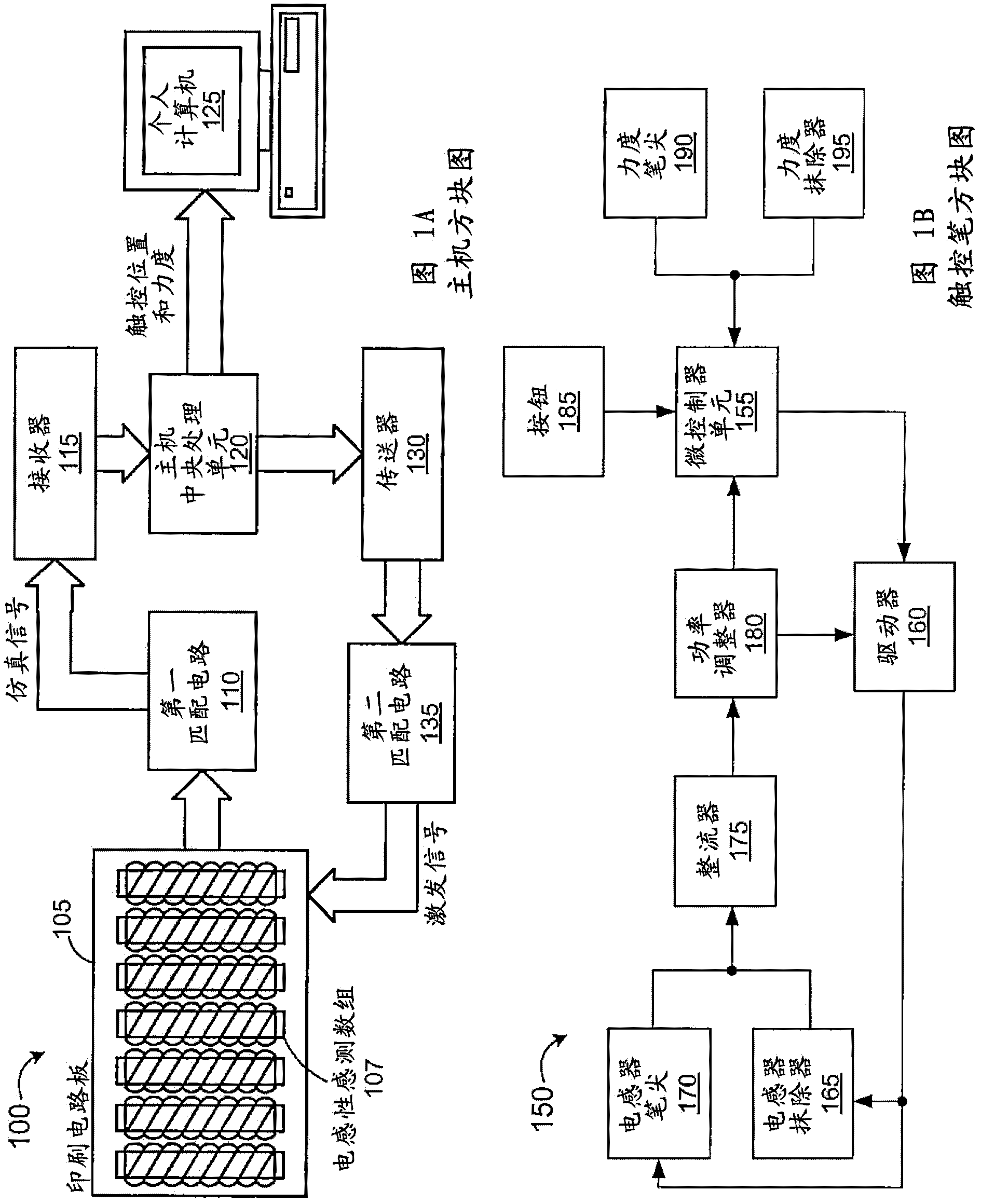
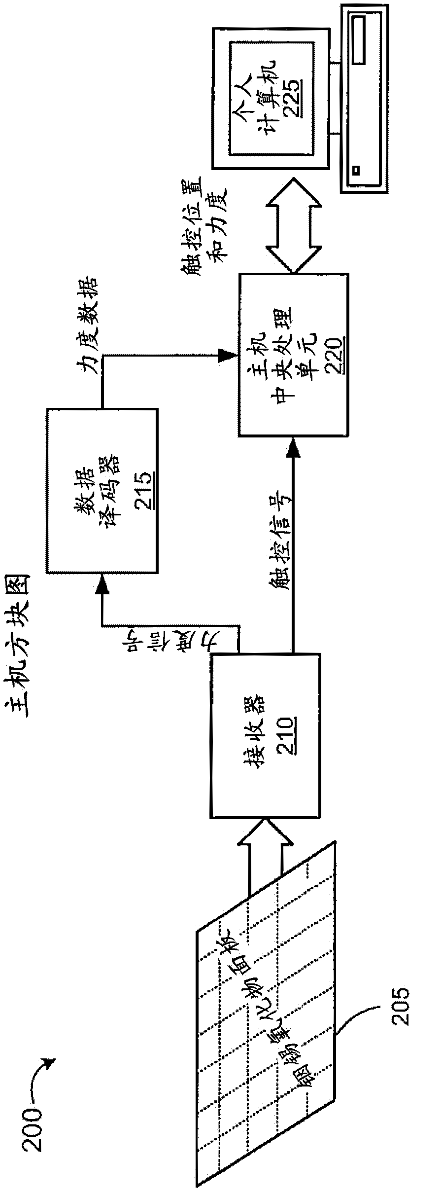
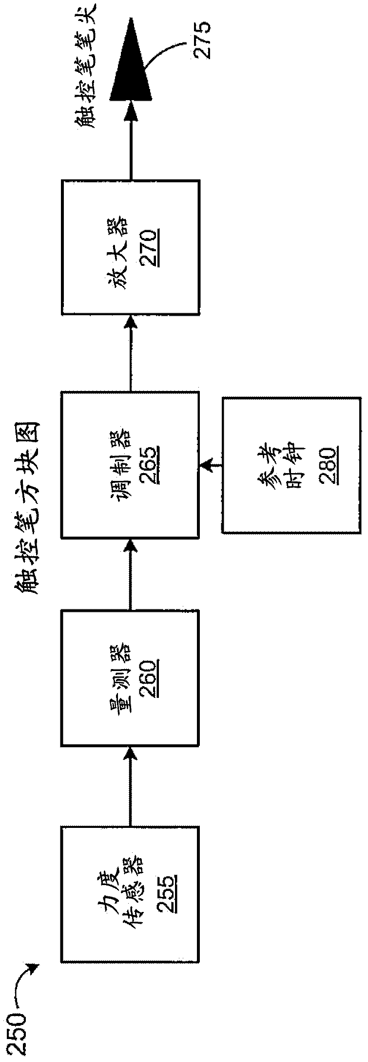
[0034] The present invention discloses an apparatus and method for synchronizing a stylus to a capacitive sensing array. In one embodiment, the stylus is configured to operate as timing "dominant", and a touchscreen controller adjusts the timing of the capacitive sense array to match when the stylus is used Timing of the stylus. The stylus capacitively couples a stylus transmit (TX) signal to the capacitive sensing array. The touch screen controller is also configured to track the position of both a passive touch object (eg, a finger) and the stylus substantially simultaneously. In one embodiment, the stylus is configured to modulate additional data to the stylus transmit signal, including but not limited to force data for the stylus tip, button data for the stylus, Acceleration of the stylus, and battery data of the stylus. In one embodiment, the touch screen controller is configured to transmit a transmit signal to the row electrodes of the capacitive sensing array and re...


PUM


Abstract

A system comprising a sensing device and a capacitive sense array configured to track the position of a stylus and synchronize the capacitive sense array to the stylus transmit signal. The system is configured to track the position of both a stylus and a passive touch object. The system is further configured to track the position of the stylus using self capacitance sensing and track the position of the passive touch object using mutual capacitance sensing. The system further configured to modulate the stylus transmit signal to include additional data to support additional stylus functions.

Description

technical field [0001] The present disclosure relates to the field of user interface devices, and more particularly to capacitor sensor devices. [0002] Cross References to Related Applications [0003] This application claims US Provisional Application No. 61 / 385,463, filed September 22, 2010, the foregoing content of which is hereby incorporated by reference. This application is related to co-pending U.S. application (application number not yet assigned) entitled "Capacitive Stylus with Palm Rejection," Attorney Docket No. CD10080, and Array Synchronized Stylus" Co-pending US Application No. CD10083 (application number not yet assigned), all of which are hereby incorporated by reference. Background technique [0004] The stylus is fully established for use with the touchscreen interface. Touch screen designs have incorporated many different technologies including resistive arrays, capacitive arrays, inductive arrays, and radio frequency sensing arrays. For example, a ...

Claims


Application Information

Patent Timeline
IPC IPC(8): G06F3/044G06F3/041G06F3/033G06F13/14G06F3/038
CPCG06F3/03545G06F3/038G06F3/044G06F3/04162G06F3/04166G06F3/0441G06F3/0442G06F3/0445G06F3/0383G06F3/0446
Inventor 大卫·G·怀特达伦·T·瓦利斯
Owner 谱瑞科技股份有限公司
Why Eureka
Try Eureka