Emergency cooling device

一种容器、储能系统的技术,应用在电池冷却/加热、电池、电气元件等方向,能够解决不实用等问题,达到高固有安全性、提高坚固性和安全性、阻止财产损失的效果

Active Publication Date: 2012-07-11
ROBERT BOSCH GMBH
View PDF4 Cites 9 Cited by
  • Summary
  • Abstract
  • Description
  • Claims
  • Application Information

AI Technical Summary

Problems solved by technology

This cannot be achieved with air or water cooling, because it is not practical to design cooling systems for such rapid and intense cooling to prevent "heat escape" especially for lithium-ion batteries, for such rapid and intense cooling of high thermal masses
[0004] In conclusion, it can be understood that the stated safety issue is a major obstacle in the commercialization of such batteries

Method used


Image

  • Emergency cooling device
  • Emergency cooling device

Examples


Embodiment Construction

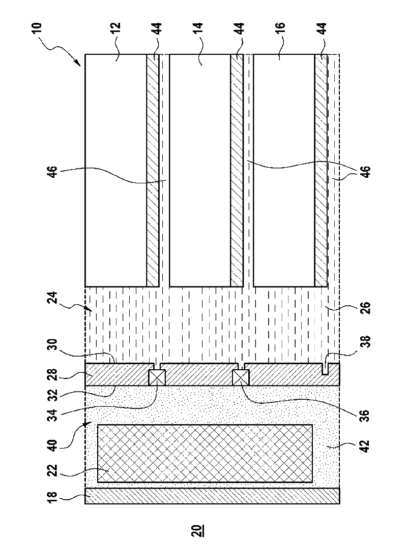
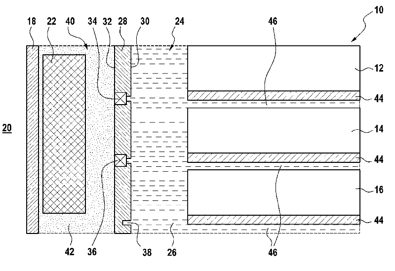
[0015] The schematic structure of the energy storage system proposed according to the invention with integrated emergency cooling can be seen from the single drawing.

[0016] The figures show energy storage systems. The energy storage system 10 includes a first container 24 and a second container 40 . In the energy storage system 10 according to the drawing, for example three battery cells are present inside the first container 24 , namely the first battery cell 12 , the second battery cell 14 and the third battery cell 16 . A first container 24 containing a number of battery cells 12 , 14 , 16 is surrounded by a first housing wall 28 .

[0017] According to the invention, by means of the energy storage system according to the drawing, devices which react undesirably at excess temperatures, in particular the battery cells 12 , 14 , 16 arranged in the first container 24 in the energy storage system 10 , can be rapidly cooled down to below the critical temperature. The energ...


PUM


Abstract

The invention relates to an energy storage system (10), particularly a battery having a number of battery cells (12, 14, 16). Said battery cells are accommodated in a first container (24). The first container (24) is separated from a second container (40) by a separating element (28), thereby ensuring a pressure difference ?p for a gas expansion from the first container (24) into the second container (40).

Description

Background technique [0001] During the development of electric vehicles and hybrid drives of vehicles with a combination of internal combustion engine and electric motor, high demands are placed on batteries in terms of energy content, service life and efficiency for future vehicle generations. In order to meet this requirement, various battery types are actively cooled, for example by means of coolants, refrigerants or by means of air. Furthermore, in batteries, for example lithium-ion batteries, it is often very useful to use the waste heat of the battery or to preheat the battery. To this end, it is often advantageous to thermally isolate the battery, so that heat losses are reduced. Furthermore, batteries in cars have reinforced housings, reducing the risk to passengers in the event of an accident or damage. For this reason, therefore, batteries are often accommodated in closed, thermally insulated housings. [0002] Some battery types, such as lithium-ion batteries, ha...

Claims


Application Information

Patent Timeline
Patent Type & Authority Applications(China)
IPC IPC(8): H01M2/10H01M2/12H01M6/50H01M10/50A62C99/00H01M50/204
CPCY02E60/12H01M2200/10A62C99/0009H01M2200/20H01M6/5038H01M10/5004H01M2/1235H01M10/5016H01M2/1016H01M10/5079H01M10/5073H01M10/625H01M10/6569H01M10/6566H01M10/613Y02E60/10H01M50/342H01M50/204
Inventor R.诺登J.法斯纳赫特
Owner ROBERT BOSCH GMBH
Why Eureka
Try Eureka