

Chuck mechanism capable of automatically changing tool accessories
An automatic tool replacement technology, applied in the field of machinery, can solve the problem that the operator can only hold it with one hand, which is inconvenient, and achieve the effect of functional versatility, quick replacement, and reduced labor intensity.
- Summary
- Abstract
- Description
- Claims
- Application Information
AI Technical Summary
Problems solved by technology
Method used
Image

Examples
Embodiment 1
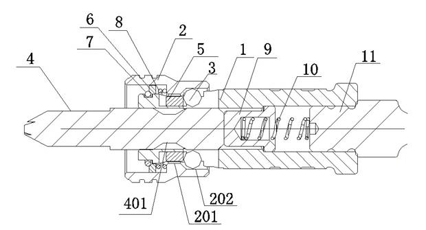
[0058] see figure 1 , the reset assembly in Example 1 includes: a washer 7 fixedly connected to the sleeve 2, a retaining ring 6 fixedly connected to the output shaft 1 for blocking the washer 7, and a spring 8. A stepped surface is formed inside the sleeve 2, and the spring 8 It is arranged between the stepped surface and the washer 7 , one end of which bears against the washer 7 and the other end bears against the stepped surface, thereby utilizing the elastic energy of the spring 8 to drive the casing 2 to reset automatically. The pop-up parts include: a central piece 11 partially arranged inside the cavity of the output shaft 1, a pop-up spring 10 connected to the central piece 11 at one end, and a sliding pin 9 provided with a spring groove for accommodating the above-mentioned pop-up spring 10, which is realized by using the elastic energy of the spring. Automatic pop-up tool attachment. Of course, in order to save raw materials, the slide pin 9 may not be provided in t...
Embodiment 2
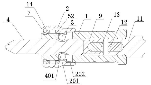
[0060] see figure 2 , as an improvement of the present invention, in Embodiment 2, the spring 8 and the washer 6 in Embodiment 1 are replaced by the return magnetic part 14, and the return magnetic part 14 is repelled by the magnetism of the attracting part 52, thereby using magnetic energy to drive the sliding Pin 9 resets automatically.
[0061] As a further improvement of the present invention, the following improvements can also be made to the pop-up assembly: a pair of mutually exclusive first pop-up magnetic pieces 13 and second pop-up magnetic pieces 12 respectively connected to the center piece 11 and the slide pin 9 are used instead of implementing In the pop-up spring in Example 1, the central piece 11 and the slide pin 9 are also provided with grooves for accommodating the first pop-up magnetic piece 12 and the second pop-up magnetic piece 13 respectively. Utilizes magnetic energy for automatic ejection of tool attachments.
Embodiment 3
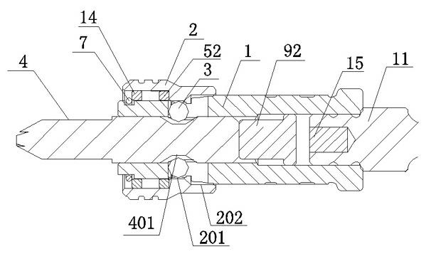
[0063] see image 3 , as another improvement of the present invention, the sliding pin 92 in Embodiment 3 is magnetic as a whole, replacing the sliding pin 9 and the second pop-up magnetic piece 13 in Embodiment 2, and there is another one that is compatible with the central piece 11 With the connected pop-up magnetic piece 15, the sliding pin 92 and the pop-up magnetic piece 15 repel each other. This solution also utilizes magnetic energy to realize automatic ejection of tool attachments.
[0064] Of course, as a further improvement of the present invention, magnets can also be used to make the central piece, instead of the central piece 11 and the pop-up magnetic piece 15, the magnetic slide pin 92 is repelled from the central piece made of magnets, and the magnetic energy is used to realize automatic The principle of the pop-up tool attachment is the same as that of the above embodiments, and will not be repeated here.
[0065] In order to ensure that the sliding pin 9 wi...
PUM
 Abstract
Description
Claims
Application Information