Time optimal grab bucket operation method

A time-optimized and operating method technology, applied in the direction of transportation and packaging, load suspension components, etc., can solve the problems that the maximum capacity of the trolley cannot be fully utilized, the installation, commissioning and maintenance work is complicated, and the cycle time cannot be guaranteed.

Active Publication Date: 2012-07-18
上海港吉电气有限公司
View PDF4 Cites 29 Cited by
  • Summary
  • Abstract
  • Description
  • Claims
  • Application Information

AI Technical Summary

Problems solved by technology

The device includes a swing angle sensor to collect the swing angle and swing frequency of the grab bucket. In practical applications, the installation, commissioning and subsequent maintenance work is more complicated
In addition, by modifying the parameters of the trolley inverter to achieve anti-sway, the maximum capacity of the trolley cannot be fully utilized, and the cycle time cannot be guaranteed to be the shortest

Method used


Image

  • Time optimal grab bucket operation method
  • Time optimal grab bucket operation method
  • Time optimal grab bucket operation method

Examples


Embodiment Construction

[0066] The present invention will be described in further detail below in conjunction with the accompanying drawings.

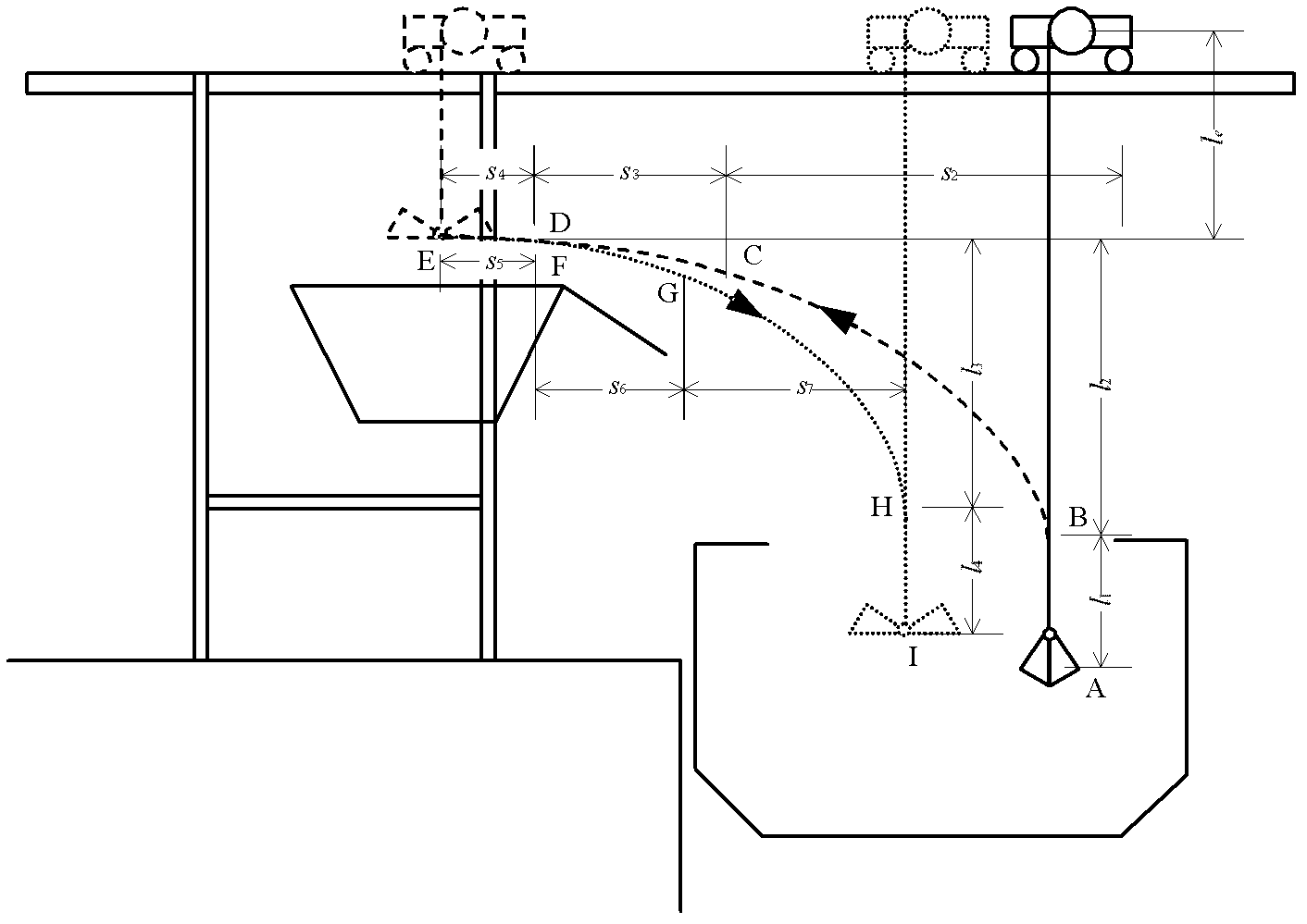
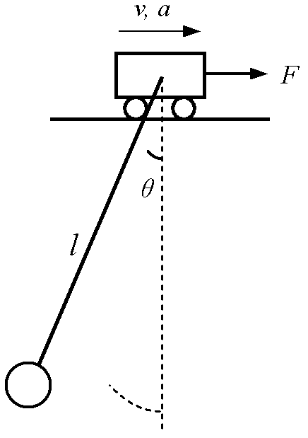
[0067] Shortening the cycle time needs to solve two problems: one is to shorten the running time of the grab bucket, and the other is to prevent the grab bucket from swinging undesirably during operation. The former problem can be solved by controlling the lifting mechanism and the trolley to move simultaneously so that the grab runs along the shortest path. The latter problem is the swing control problem, which needs to control the movement of the trolley so that the grab does not produce undesired swings. These two issues need to be considered simultaneously. For the sway control problem, experienced drivers usually use the method of following the car to eliminate the swing of the grab, which means that when the car accelerates / decelerates in a specific way, the residual swing of the grab may be zero. Therefore, the first problem that needs to be solved i...


PUM


Abstract

The embodiment of invention discloses a time optimal grab bucket operation method. According to the method, an operation path of a grab bucket is a parabola compounded by hosting motion and trolley motion; the hoisting motion operates according to a trapezoidal velocity curve; both ascending motion and descending motion are accelerated to operate at full speed with the maximum acceleration and decelerated to stop with the maximum acceleration when a target location is reached, so that the grab bucket operates at high level at the earliest time and descends from the high level at the latest time; for the trolley motion, a two-step acceleration method is adopted at an acceleration stage, a two-step deceleration method is adopted at a deceleration stage, a two-step deceleration method or a bucket throwing deceleration method is adopted at the stage of approaching a hopper, and a two-step acceleration method or a bucket throwing acceleration method is adopted at the stage of leaving the hopper, wherein the hoisting motion is accelerated to the full speed, a trolley starts to move from a point B, and the grab bucket starts to move along the parabolic path; and when the grab bucket returns to a cabin of a ship, the grab bucket moves to the point H along the parabolic path, the trolley stops moving, and the hoisting starts to decelerate from the point H and stops at a point I.

Description

technical field [0001] The invention relates to the technical field of crane control, in particular to a method for the lifting of a ship unloader and the combined movement of a trolley, which effectively controls the swing of a grab bucket and optimizes the running time of the grab bucket. Background technique [0002] Grab ship unloaders are often found in bulk cargo terminals, and use grabs to move bulk cargo such as coal, ore, and grain from the cabin to the hopper on the ground. The grab is connected with the hoisting mechanism and the trolley mechanism through a wire rope, and is driven by the vertical lifting movement and the horizontal trolley movement. The ship unloading operation is a process in which the grab bucket makes periodic reciprocating movements between the cabin and the hopper. A reciprocating movement of the grab is called a working cycle, such as figure 1 As shown, a typical job cycle includes the following steps: [0003] (1) The grab is closed in ...

Claims


Application Information

Patent Timeline
Patent Type & Authority Applications(China)
IPC IPC(8): B66C13/04
Inventor 孙斌顾晓
Owner 上海港吉电气有限公司
Why Eureka
Try Eureka