Cover glass for flat panel displays

A technology for flat panel display and protective glass, which is applied in glass forming, glass tempering, glass forming, etc. It can solve the problems of strength reduction and achieve the effects of suppressing the generation of defects, preventing spontaneous damage, and reducing the production rate

Inactive Publication Date: 2012-07-18
ASAHI GLASS CO LTD
9 Cites 5 Cited by

AI-Extracted Technical Summary

Problems solved by technology

When the thickness of the glass is reduced, the strength will decrease. In order to solve this problem, it is curren...

Method used

[0083] By setting the heating temperature of the molten salt to 350° C. or higher, it is possible to prevent chemical strengthening from being difficult due to a decrease in ion exchange rate. Moreover, by setting the heating temperature of molten salt to 500 degreeC or less, decomposition and deterioration of molten salt can be suppressed.
[0092] As shown in FIG. 4...

Abstract

A cover glass for flat panel displays, which is difficult to be spontaneously destroyed is provided. The present invention relates to a cover glass for flat panel displays, obtained by chemically strengthening a glass obtained by a fusion process, in which the glass before chemical strengthening does not contain defects having a particle size of 40 [mu]m or more, and the cover glass has an internal tensile stress of 30 MPa or more and a thickness of 1.5 mm or less.

Application Domain

Glass forming apparatusGlass tempering apparatus +1

Technology Topic

Cover glassFlat panel +1

Image

  • Cover glass for flat panel displays
  • Cover glass for flat panel displays
  • Cover glass for flat panel displays

Examples

  • Experimental program(1)

Example Embodiment

[0099] Example
[0100] Hereinafter, the present invention will be described with reference to Examples, but the present invention is not limited to these Examples.
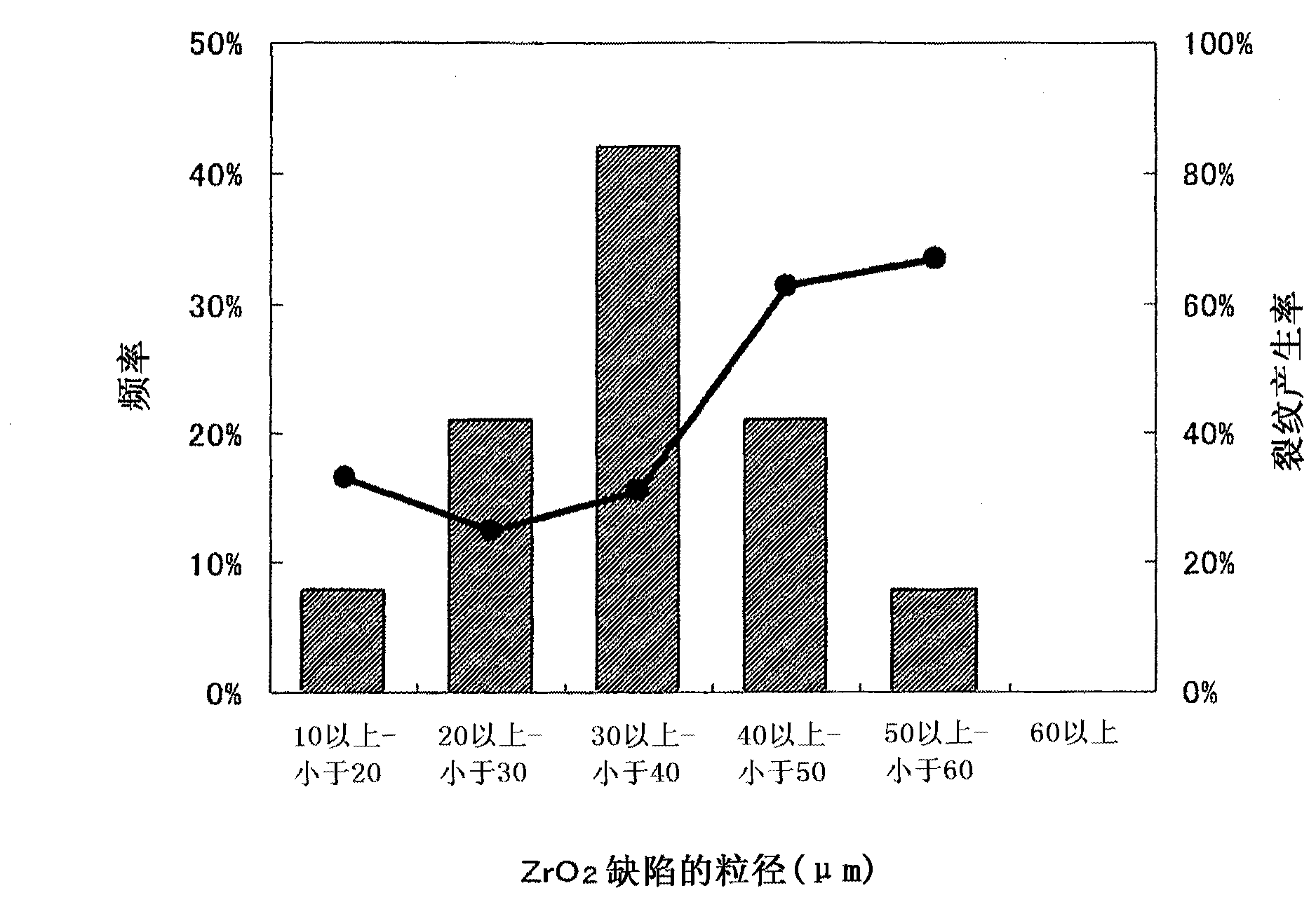
[0101] Glass manufactured by the fusion method [composition (mol %): SiO] was measured using optical microscope photographs of 38 samples 2 66.6%, Al 2 O 3 10.8%, Na 2 O 13.2%, K 2 The particle size (diameter) of defects in O 2.4%, MgO 6.2%, CaO 0.6%], and the frequency in each particle size range was calculated. The particle size of the defect was determined by comparing the length of the largest portion with the photograph of the objective micrometer. The results are shown in figure 1 bar chart.
[0102] Moreover, the generation rate of cracks in the said glass was measured. Here, the occurrence rate of cracks is measured by visually determining whether or not cracks have occurred in the micrograph. The results are shown in figure 1 line chart.
[0103] like figure 1 As shown in the line graph of , when the particle size (diameter) of the defect is 40 μm or more, the occurrence rate of cracks increases sharply. In addition, the composition of defects was analyzed by EPMA, and the result was ZrO 2. From this result, as long as there are no defects having a particle size of 40 μm or more in the glass for chemical strengthening, the possibility of spontaneous destruction after chemical strengthening is very low.

PUM

no PUM

Description & Claims & Application Information

We can also present the details of the Description, Claims and Application information to help users get a comprehensive understanding of the technical details of the patent, such as background art, summary of invention, brief description of drawings, description of embodiments, and other original content. On the other hand, users can also determine the specific scope of protection of the technology through the list of claims; as well as understand the changes in the life cycle of the technology with the presentation of the patent timeline. Login to view more.
Why Eureka
Try Eureka