
Method for determining migration velocity of displacement front in CO2 miscible displacement physical simulation

A miscible flooding and CO2 technology, which can be used in earth-moving drilling, fluid production, wellbore/well components, etc., and can solve the problems of inability to accurately grasp the occurrence state and migration process of fluids.

Inactive Publication Date: 2012-07-18
DALIAN UNIV OF TECH
View PDF2 Cites 7 Cited by
  • Summary
  • Abstract
  • Description
  • Claims
  • Application Information

AI Technical Summary

Problems solved by technology

However, with conventional experimental methods, the actual formation model can only be regarded as a "black box", and the oil displacement status can only be analyzed by monitoring the flow rate and pressure of injection and production. This experimental method cannot accurately grasp the fluid flow in porous media. Occurrence state and migration process, obviously there are certain limitations

Method used


Image

  • Method for determining migration velocity of displacement front in CO2 miscible displacement physical simulation
  • Method for determining migration velocity of displacement front in CO2 miscible displacement physical simulation
  • Method for determining migration velocity of displacement front in CO2 miscible displacement physical simulation

Examples


specific Embodiment approach

[0023] (1) Determine the oil saturation distribution at different positions in the porous media

[0024] Taking MRI technology as an example, first obtain an image I o0 , and then obtain another image I during the displacement process oi , then the oil saturation in any small voxel is:

[0025] S oi ( x , y , z ) = I oi ( x , y , z ) I o 0 ( x , y , z ) - - ...


PUM


Abstract

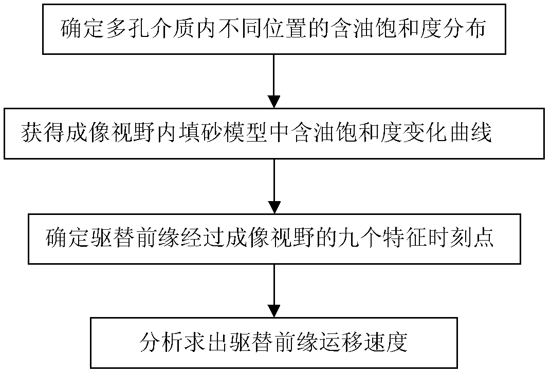
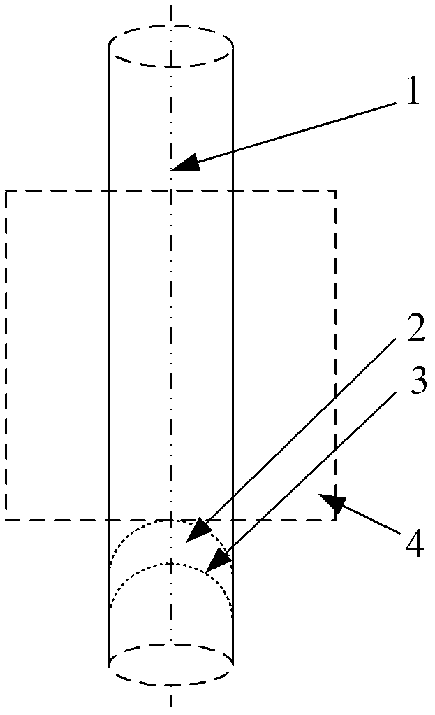
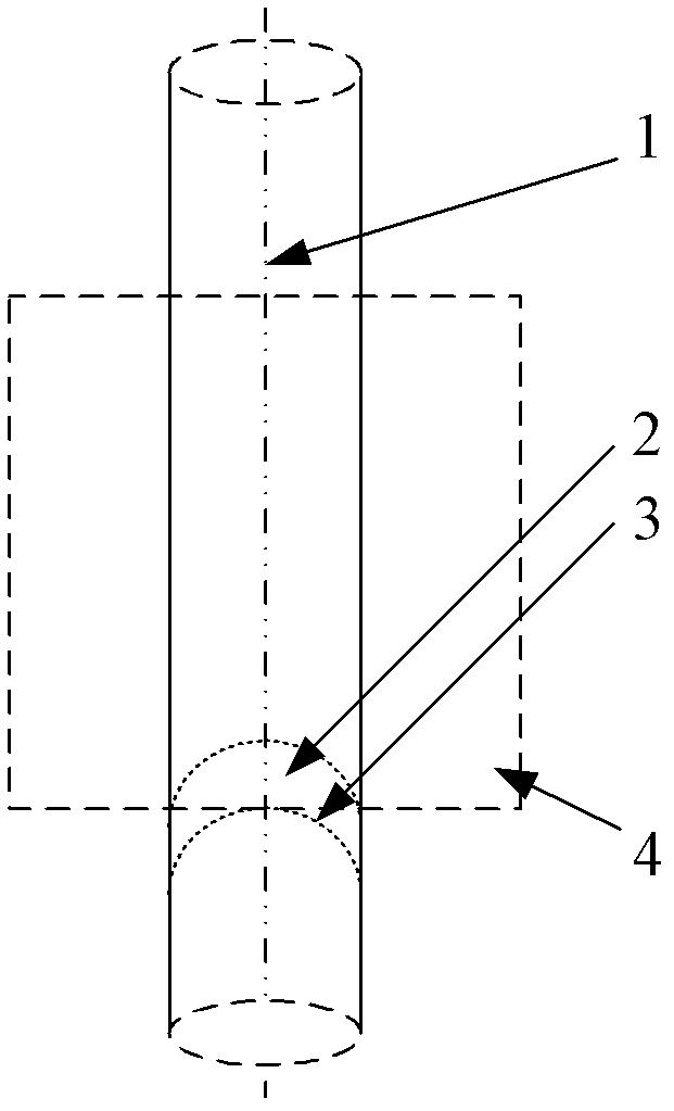
The invention discloses a method for determining the migration velocity of a displacement front in CO2 miscible displacement physical simulation, belonging to the detection field of oil pool physical simulation. The method for determining the migration velocity of a displacement front in CO2 miscible displacement physical simulation comprises the following steps of: firstly, determining the oil saturation distribution in different positions in a porous medium by use of the imaging technology; obtaining the oil saturate change curve in a sand filling model in the imaging view field; then, determining the characteristic moment point passing through the imaging view field of the displacement front; and finally, obtaining the migration velocity of the displacement front by use of an analysis method. The method can determine the migration velocity of the displacement front in the CO2 miscible displacement process and accurately obtain the flowing law of CO2 in the oil-containing porous medium so as to provide analysis basis for the nondestructive detection in the CO2 miscible displacement physical simulation process.

Description

technical field [0001] The present invention relates to a method for determining CO 2 A method for displacement front migration velocity in miscible flooding physical simulation belongs to the field of reservoir physical simulation detection. Background technique [0002] will CO 2 Injection into oil reservoirs can not only enhance oil recovery and generate huge economic benefits, but also achieve CO 2 Geological storage to solve CO 2 Therefore, this method should be an effective way to solve the conflicting problems of human development and environmental improvement. by CO 2 Flooding technology can further increase oil recovery by 10%-15% on the basis of conventional technology, so further in-depth research on the use of CO 2 Issues related to enhanced oil recovery technology are necessary. However, with conventional experimental methods, the actual formation model can only be regarded as a "black box", and the oil displacement status can only be analyzed by monitorin...

Claims


Application Information

Patent Timeline
IPC IPC(8): E21B47/002E21B43/22
Inventor 赵越超宋永臣刘瑜朱宁军王同雷王合明宿博
Owner DALIAN UNIV OF TECH
Learn More