Structure having two independent turbochargers of combustion engines and operating method thereof

A technology for turbochargers and internal combustion engines, applied to internal combustion piston engines, combustion engines, machines/engines, etc., can solve the problem of high cost and achieve the effect of reducing wear and tear

Inactive Publication Date: 2012-07-18
AUDI AG
View PDF5 Cites 4 Cited by
  • Summary
  • Abstract
  • Description
  • Claims
  • Application Information

AI Technical Summary

Problems solved by technology

Wear parts have to be replaced especially in pairs, which leads to prohibitive costs

Method used


Image

  • Structure having two independent turbochargers of combustion engines and operating method thereof
  • Structure having two independent turbochargers of combustion engines and operating method thereof
  • Structure having two independent turbochargers of combustion engines and operating method thereof

Examples


Embodiment Construction

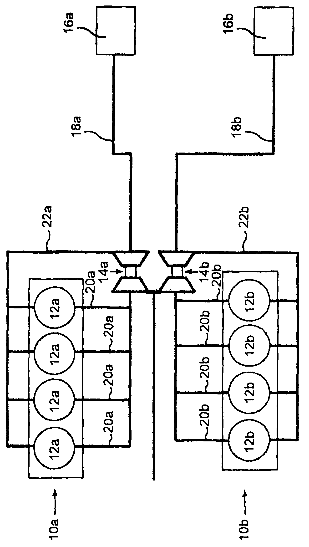
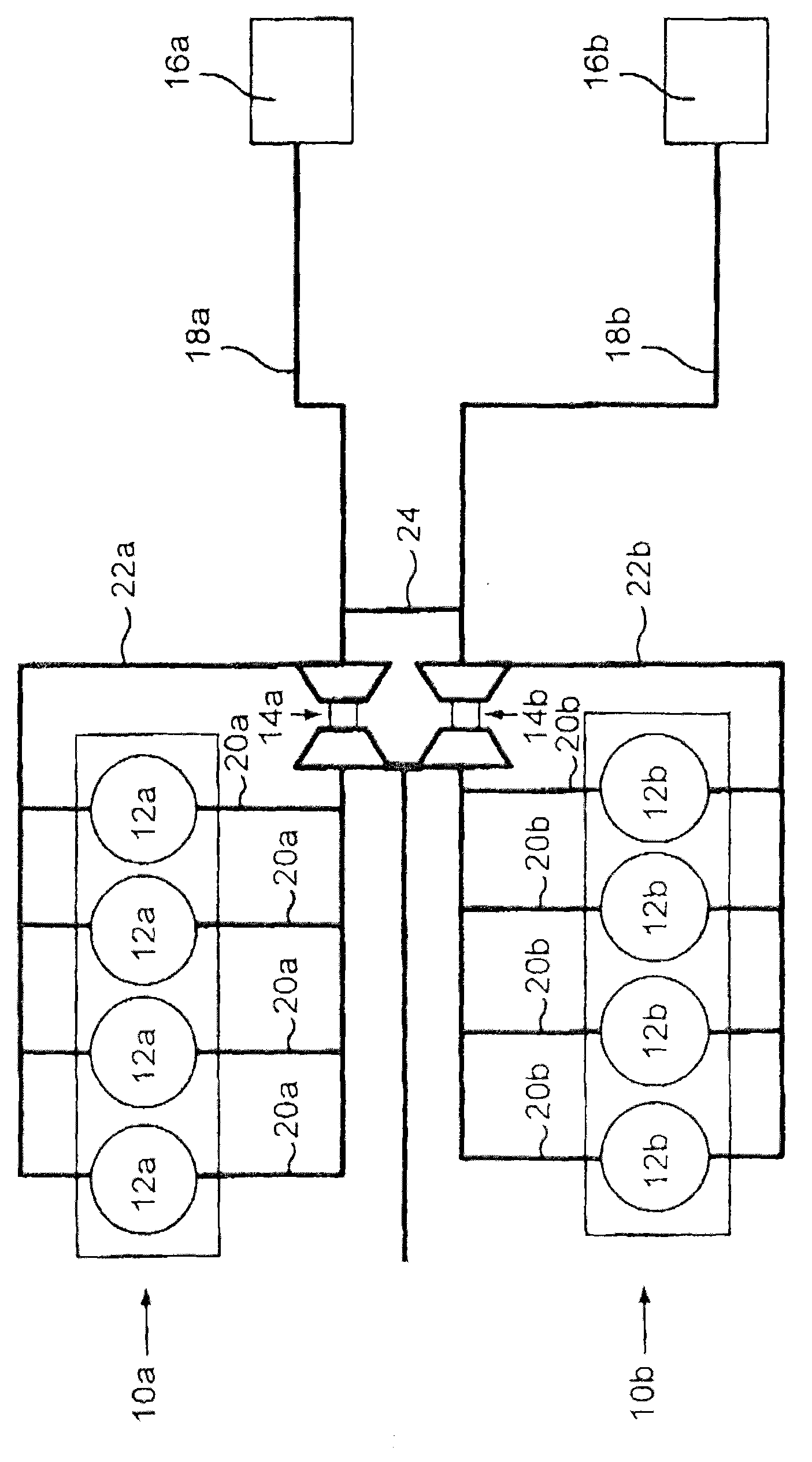
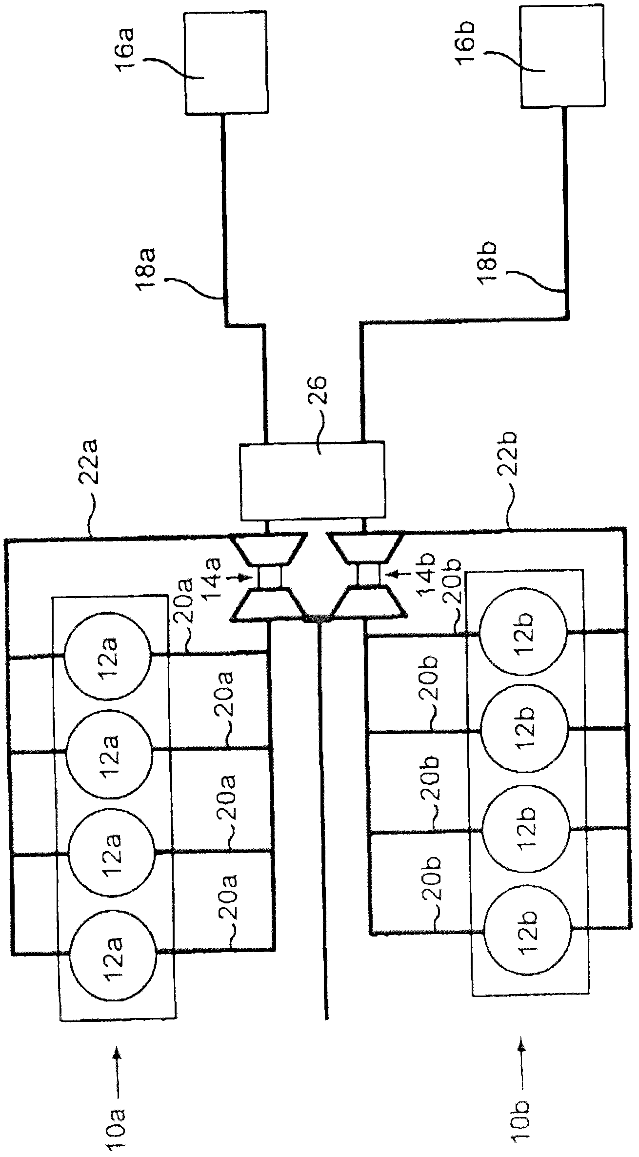
[0016] The internal combustion engine has two cylinder banks 10a, 10b which each have four cylinders 12a or four cylinders 12b. A turbocharger 14a is assigned to the first cylinder bank 10a and a turbocharger 14b is assigned to the second cylinder bank 10b. The purpose of the turbocharger is to press filtered air (clean air) into the cylinders and to utilize the pressure of the exhaust gases expelled from the cylinders there. In this case, a clean air filter 16a, 16b is assigned to each turbocharger 14a, 14b, and a clean air line 18a, 18b is connected downstream of the clean air filter 16a, 16b. The air (charge air) compressed by each turbocharger 14a, 14b is then directed to the cylinder 12a or 12b via conduit 20a or 20b. The exhaust gas recirculation line 22a or 22b guides the exhaust gas to the turbocharger 14a or 14b.

[0017] According to the prior art, the two turbochargers 14a, 14b work completely independently of each other, there is no connection between the clean a...


PUM


Abstract

The present invention relates to a structure having internal combustion engines (10a, 10b) which have two independent turbochargers (14a, 14b). The air filtered via clean air filters (16a, 16b) is input into the turbochargers (14a, 14b) respectively through clean air tubes (18a, 18b), wherein a pressure balance for the air entering into the two clean air tubes (18a, 18b) is formed. A fluid tube (24) can interconnect the two clean air tubes (18a, 18b). And an air collecting container (26) also can be arranged.

Description

technical field [0001] The invention relates to an arrangement with an internal combustion engine to which two mutually independent turbochargers are assigned. Typically each turbocharger applies charge air to a set of combustion chambers. The group of combustion chambers can in particular be a cylinder bank / block. In this construction, filtered air is introduced into the two turbochargers via a clean air line, wherein a separate clean air filter can be provided for each turbocharger and thus for each clean air line. Background technique [0002] DE 36 33 405 C2, DE 10 2005 054 249 A1 and DE 10 2007 014 319 A1 each disclose an arrangement of the above-mentioned type, in which the clean air lines downstream of the respective turbochargers are connected to each other on the charge air side, ie in the direction of flow. This structure is adopted in particular for pressure equalization. [0003] The turbocharger in this known construction is subject to severe wear. Wear part...

Claims


Application Information

Patent Timeline
Patent Type & Authority Applications(China)
IPC IPC(8): F02B37/007
CPCF02M35/10019F02M35/0215F02M35/10157F02B33/44F02B37/007Y02T10/144F02M35/10308Y02T10/12
Inventor A·阿达摩尔H·施瓦姆勒
Owner AUDI AG
Why Eureka
Try Eureka