Pneumatic actuator of valve

A technology of pneumatic actuators and valves, which is applied in the field of valve controllers and pneumatic actuators, can solve problems such as poor safety and reliability, and achieve high reliability, prevent malfunctions, and control safety.

Active Publication Date: 2012-07-18
浙江伯特利科技股份有限公司
View PDF5 Cites 3 Cited by
  • Summary
  • Abstract
  • Description
  • Claims
  • Application Information

AI Technical Summary

Problems solved by technology

However, the working state of the existing pneumatic actuator is completely controlled by the main control solenoid valve. When the control of the main control sol

Method used


Image

  • Pneumatic actuator of valve
  • Pneumatic actuator of valve

Examples


Embodiment Construction

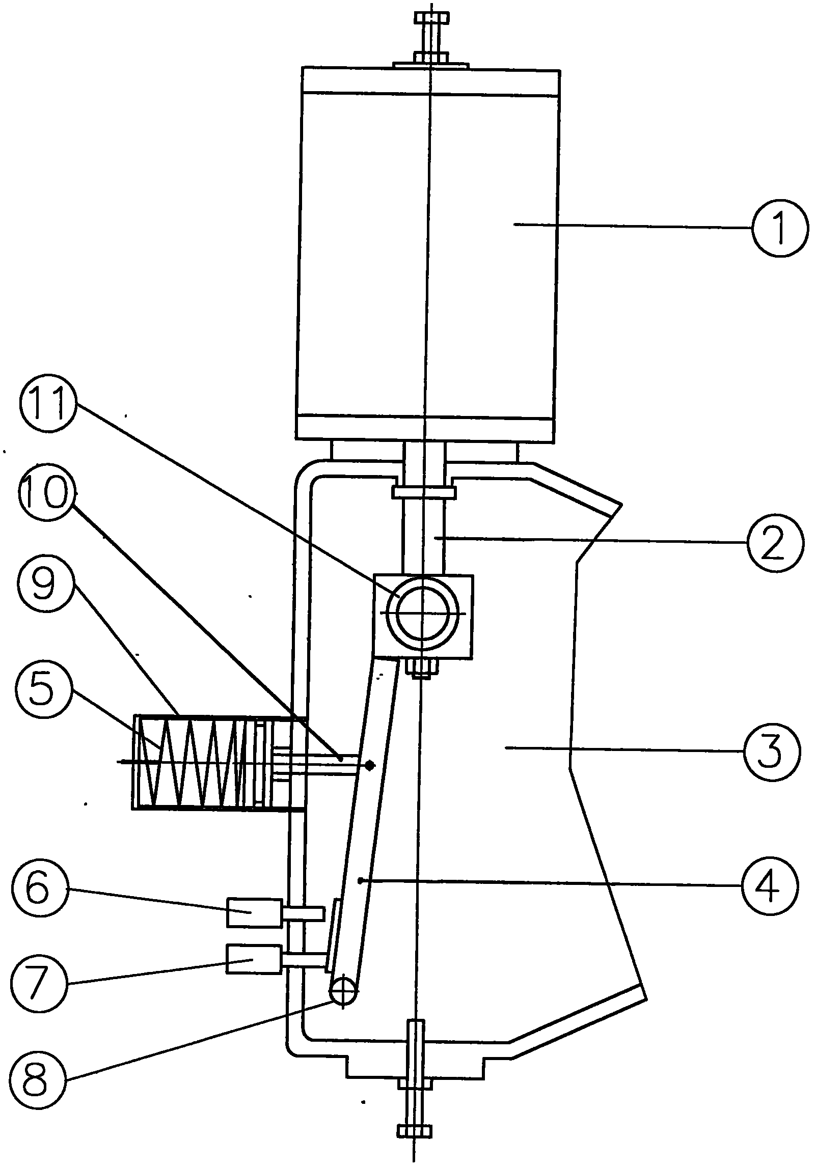
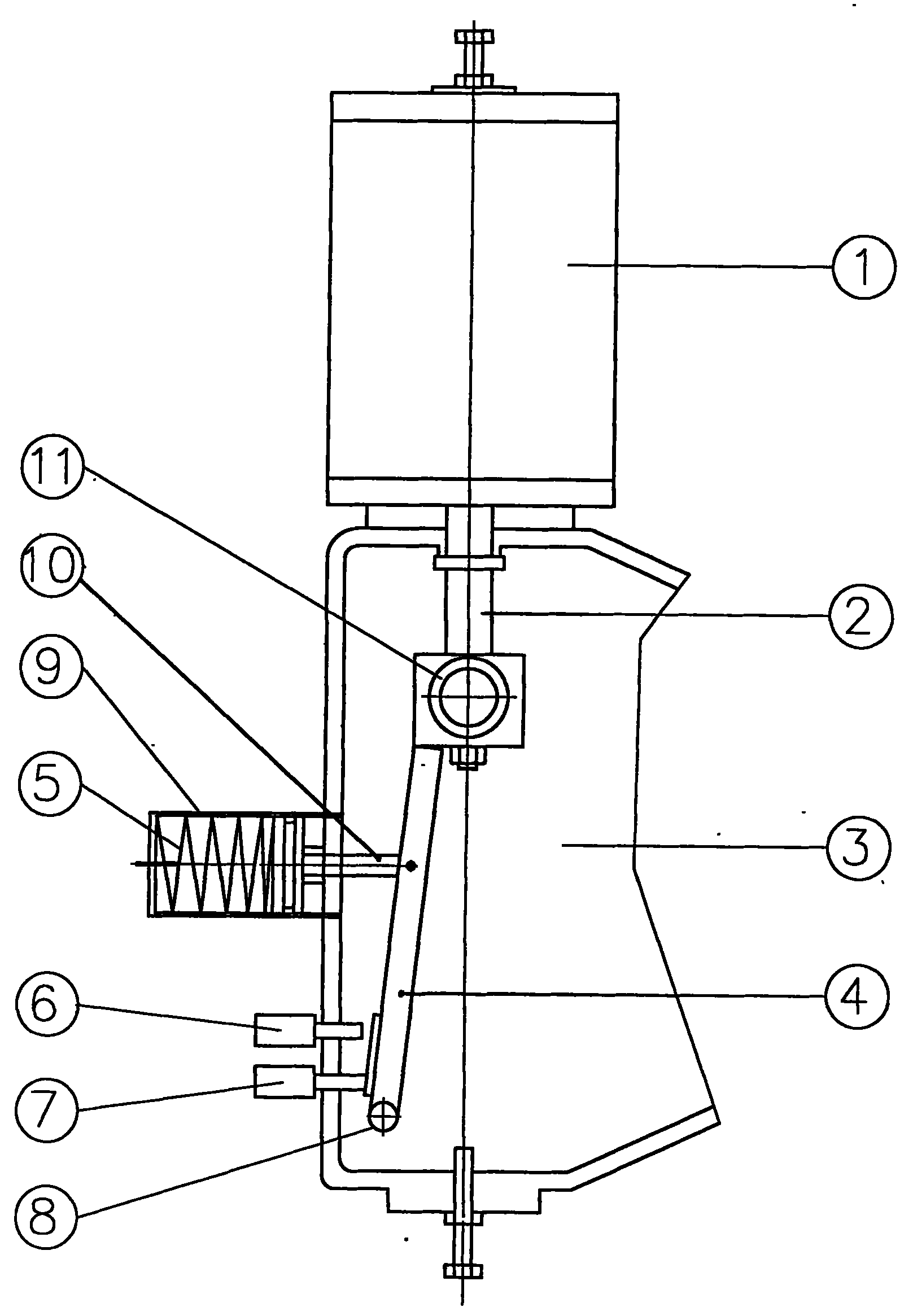
[0009] Such as figure 1 The valve pneumatic actuator shown includes a housing 3 and a cylinder 1. The housing 3 is provided with a connecting piece fixedly connected to the valve. The cylinder 1 is fixedly installed on the housing 3. One end of the piston rod 2 is connected to the The piston is fixedly connected, and the other end is fixedly connected with the valve stem of the controlled valve through the transmission device installed in the housing 3. When the valve is closed, the piston rod 2 retracts into the cylinder 1. When the valve is open, the piston rod 2 retracts from the cylinder. 1, the working air source of cylinder 1 is controlled by the main control solenoid valve. There is a safety lock on the piston rod 2, the safety lock is composed of a lock rod 4, a lock block 11 and a control cylinder 9, the lock block 11 is fixedly installed on the end of the piston rod 2, and the end of the lock rod 4 away from the cylinder 1 is hinged by a rotating shaft 8 In the hous...


PUM


Abstract

The invention relates to a pneumatic actuator of a valve, which comprises a casing and an air cylinder. The casing is provided with a connector fixedly connected with the valve, and the air cylinder is fixedly mounted on the casing. One end of a piston rod is fixedly connected with a piston in the air cylinder, and the other end of the piston rod is fixedly connected with a valve stem through a drive device in the casing. The pneumatic actuator is characterized in that a safety lock is arranged on the piston rod and is locked and controlled by signals of a pressure switch of a pressure sensorin a controlled container (digester) and signals of an off travel switch. When the internal pressure of the controlled container (digester) exceeds the set pressure or when a controlled valve is switched off, the pressure switch and the off travel switch are cut off, a lock control electromagnetic valve is powered off, a control spring pushes a lock bar to butt against the lower end face of a lock block, and the safety lock is locked to prevent the piston rod from moving and avoid error action of an overhead valve of the digester. Accordingly, the pneumatic actuator of the valve has the advantages of high control safety and reliability and the like, and is suitable to be used with the overhead valve of the pulp digester.

Description

technical field [0001] The invention relates to a valve controller, in particular to a valve pneumatic actuator. The invention is suitable for the pneumatic actuator of the top valve of the pulp digester. Background technique [0002] In the papermaking process, the digester is the key equipment for converting wood chips and other raw materials into pulp through chemical reaction. In order to prevent environmental pollution caused by the leakage of the medium in the digester, there are high requirements for the sealing performance and control reliability of the top valve of the digester. At present, the opening and closing of the top valve of the digester is generally controlled by a pneumatic actuator, and the pneumatic actuator is controlled by the main control solenoid valve. The air source of the pneumatic actuator is controlled by the main control solenoid valve to control the top valve of the digester. However, the working state of the existing pneumatic actuator is c...

Claims


Application Information

Patent Timeline
IPC IPC(8): F16K31/122F16K35/00
Inventor 金克雨秦永亚黄俊荣
Owner 浙江伯特利科技股份有限公司
Why Eureka
Try Eureka