Eureka AIR delivers breakthrough ideas for toughest innovation challenges, trusted by R&D personnel around the world.

Method for expanding application bandwidth of spatial heterodyne interferometer

A space heterodyne and interferometer technology, applied in the field of optics, achieves the effect of simple information analysis and inversion and high radiation flux

Inactive Publication Date: 2014-05-07
ANHUI INST OF OPTICS & FINE MECHANICS - CHINESE ACAD OF SCI
View PDF2 Cites 2 Cited by
  • Summary
  • Abstract
  • Description
  • Claims
  • Application Information

AI Technical Summary

Problems solved by technology

[0005] The purpose of the present invention is to provide a method for expanding the application bandwidth of the spatial heterodyne interferometer to solve the problem that the spatial heterodyne interferometer can only obtain extremely high spectral resolution in a narrow spectral range in the prior art

Method used


Image

  • Method for expanding application bandwidth of spatial heterodyne interferometer
  • Method for expanding application bandwidth of spatial heterodyne interferometer
  • Method for expanding application bandwidth of spatial heterodyne interferometer

Examples

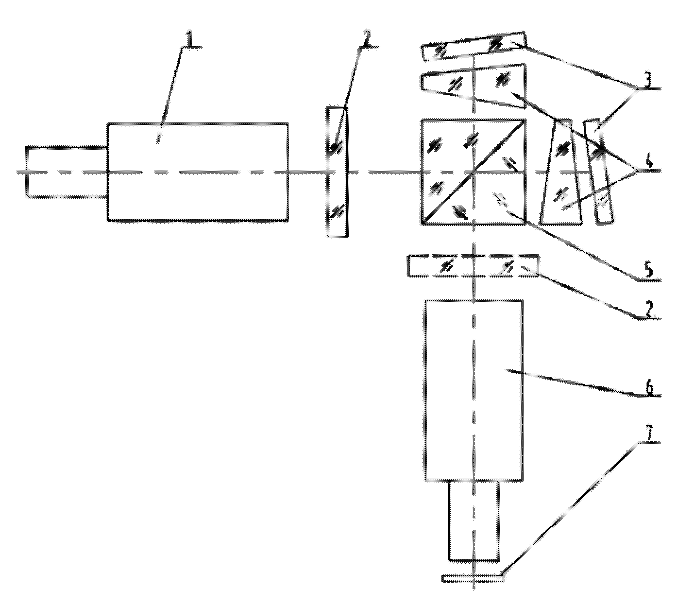

Embodiment Construction

[0024] Below in conjunction with accompanying drawing, the present invention will be further described through embodiment.

[0025] see figure 1 , the method for expanding the application bandwidth of the spatial heterodyne interferometer includes a spatial heterodyne interferometer, a grating 3, a field-of-view prism 4, a detector 7, and an imaging lens 6, and the spatial heterodyne interferometer includes a collimator lens 1, a splitter A beam splitter 5, a grating 3 is respectively arranged above and behind the beam splitter 5, a field-of-view prism 4 is also arranged between the beam splitter 5 and the grating 3, an imaging lens 6 is arranged below the beam splitter 5, and an imaging lens 6 is arranged below the beam splitter 5 for imaging A detector 7 is arranged under the lens 6, and a bidirectional filter 2 is arranged between the beam splitter 5 and the collimating lens 1, or between the imaging lens 6;

[0026] The implementation method includes the following impleme...


PUM


Abstract

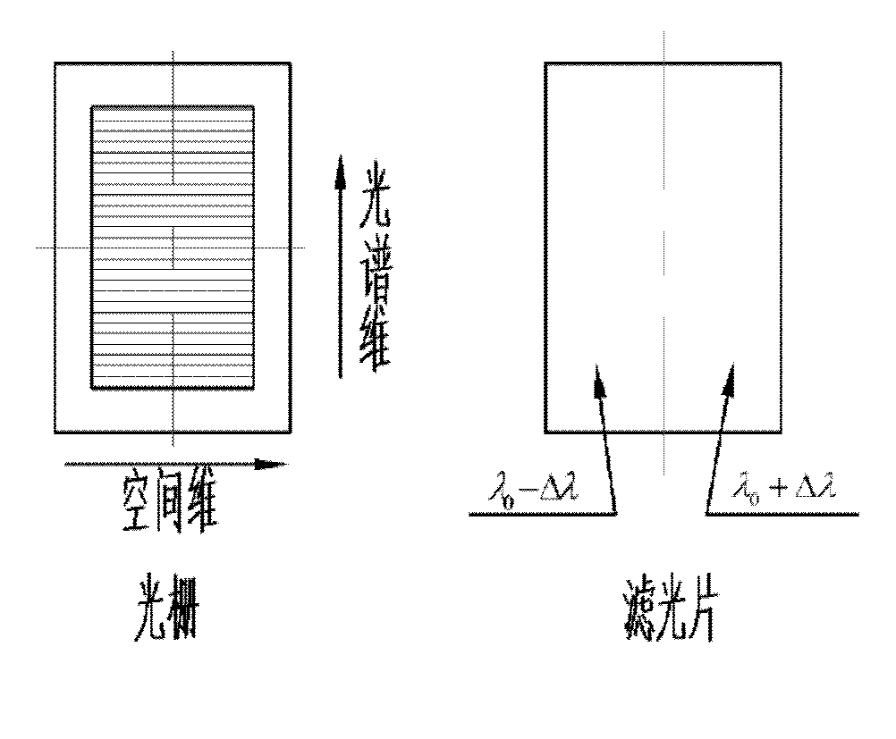
The invention discloses a method for expanding the application bandwidth of a spatial heterodyne interferometer. An optical filter is arranged in parallel optical paths with a tiny view field angle, wherein the optical paths are emitted by a collimation lens; the bidirectional optical filter is divided into two parts in a grating scribed line direction; different film coating parameters respectively and correspondingly cut off the optical spectrums of a long wave and a short wave of the base frequency lamda0 application bandwidth of the spatial heterodyne interferometer; and the optical spectrums are zoomed in proportion by an imaging lens to finally obtain an optical spectrum interferogram on in negative direction and the positive direction of the base frequency on a detector. Compared with the traditional spatial heterodyne interferometers, the spatial heterodyne interferometer disclosed by the invention is characterized in that target band width is effectively monitored to multiply on the premise of guaranteeing the constant spectral resolution. The technical problem that the number of the detector image element needs to be increased or the spectral resolution needs to be lowered because the spatial heterodyne interferometer increases the effective application bandwidth in the background prior is solved.

Description

technical field [0001] The invention relates to the field of optics, in particular to a method for extending the application bandwidth of a spatial heterodyne interferometer. Background technique [0002] The spatial heterodyne spectrometer can obtain extremely high spectral resolution in a narrow spectral range, and increasing its effective bandwidth can be achieved by increasing the number of detector pixels or reducing the spectral resolution. [0003] The spatial frequency of the detector remains unchanged, the number of pixels is increased to expand the bandwidth, and the zoom ratio of the imaging lens and the grating density remain unchanged, the effective aperture of the imaging and collimating lens matched by the spatial heterodyne interferometer is doubled, This increases the size of the entire system structure. Due to the increase of the clear aperture of the front and rear lenses, the aberration increases, and the lens needs to be redesigned and optimized. At th...

Claims


Application Information

Patent Timeline
Patent Type & Authority Patents(China)
IPC IPC(8): G01J3/45
Inventor 熊伟罗海燕施海亮李双
Owner ANHUI INST OF OPTICS & FINE MECHANICS - CHINESE ACAD OF SCI
Why Eureka
Eureka Blog
Learn More